T 3000 - T 350
2
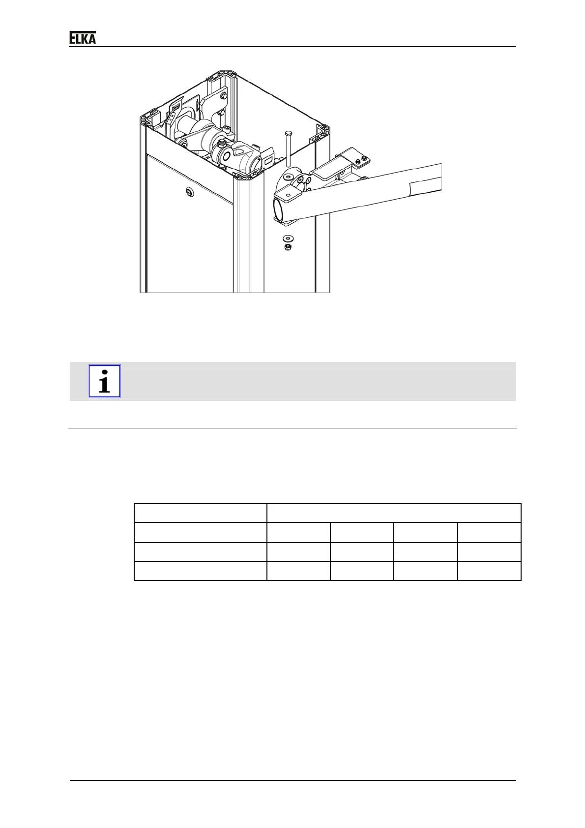
Drawing 15
4. Connect the barrier boom to the boom connector using the screw M8x90.
Tighten the fastening nut with a max. torque of 20Nm.
5. Push the boom into the clips.
Emergency release during current failure etc.
7.7 Balancing springs
1. Place the barrier boom manually in position OPEN.
2. Mount the number of balancing springs according to the boom length (see
table below).
Boom length [mm]
Model
2,000 2,500 3,000 3,500
T 3000 2x F1.1 2x F1.1 2x F1.1 ---
T 3500 2x F1.1 2x F1.1 2x F1.1 3x F1.1
Table6
Pressure spring type F1.1 = Balancing spring
Wire diameter 5mm
For barriers up to 3,500mm boom length
3. During installation of the balancing springs please observe the correct
positioning in the spring assembly (see drawing below – positions of the
pressure springs on the support plate).
 Loading...