EasyManua.ls Logo

Elkay EZSTL8WS 1G Series User Manual

Elkay EZSTL8WS 1G Series
18 pages
To Next Page IconTo Next Page
Page #1 background imageLoading...
Page #1 background image
Page 1 1000002243 (Rev. E - 01/19)
EZSTLDWS*1G EZSTL8WS*1G, 2G, 3G LZSTLDWS*1G LZSTL8WS*1G, 2G, 3G
EZ™ & LZ™ Stations versatile de Remplissage de Bouteille Série et Refroidisseurs
EZ™ & LZ™ Serie versatil Botella Bombas y Enfriadores
EZ
& LZ™ Series Versatile Bottle Filling Stations & Coolers
INSTALLATION & USE MANUAL
Manual de instalación y uso
Manuel d’installation et utilisation
*Versatile Cooler Model LZSTL8WSLK
conguration as shipped
*Versatile Cooler Model LZSTL8WSLK
alternate installations
*Versatile cooler design allows units to be
installed either left-hand high and right-hand low
or left-low and right high.
Basin change may be required. See desired
rough-in to help determine if the basin change is
necessary.
Question and Answer IconNeed help?

Do you have a question about the Elkay EZSTL8WS 1G Series and is the answer not in the manual?

Elkay EZSTL8WS 1G Series Specifications

General IconGeneral
BrandElkay
ModelEZSTL8WS 1G Series
CategoryWater Dispenser
LanguageEnglish

Summary

Standard Rough-In Installation

Left-Hand High, Bottle Filler Low Models

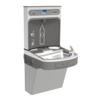
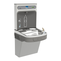
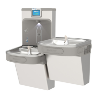
Specifies rough-in dimensions for left-hand high, low bottle filler models.

Alternate Right-Hand High, Bottle Filler Low Models

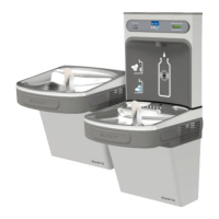
Specifies alternate rough-in for right-hand high, low bottle filler models.

Alternate Right-Hand High, Bottle Filler High Models

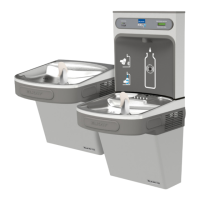
Specifies alternate rough-in for right-hand high, high bottle filler models.

Alternate Left-Hand High, Bottle Filler High Models

Specifies alternate rough-in for left-hand high, high bottle filler models.

Cooler Installation and Maintenance

Hanger Bracket and Cooler Mounting

Instructions for securely mounting the cooler using hanger brackets.

Cooler Exterior Cleaning

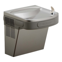
Guidance on cleaning unit exterior panels using mild soap and water.

Service Procedures

Shroud Access and Removal

Steps for removing upper and lower shrouds to access internal components.

Bubbler Service and Repair

Procedures for servicing or replacing the bubbler assembly.

Push Bar Switch Operation Explanation

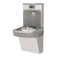
Description of how the push bar activates the water dispensing switch.

Bottle Filler Installation

Control Board Programming

Verify Control Board Software Version

Steps to check the control board software designation.

Accessing Programming Functions

How to locate and use the programming button for settings adjustments.

Resetting the Filter Monitor

Procedure to reset the visual filter monitor after filter replacement.

Setting the IR Sensor Range

Adjusting the range for the IR sensor to optimize water dispensing detection.

Configuring Unit Type (Refrigerated/Non-Refrigerated)

Setting the unit type for correct operational parameters.

Resetting the Bottle Count

Procedure to reset the bottle dispensing counter to zero.

Setting Filter Capacity

How to input the specific capacity of the installed water filter.

Alternate Mounting Instructions

Moving Bottle Filler and Basin (Non-Refrigerated)

Instructions for relocating the bottle filler and basin to the left side for alternate mounting.

Alternate Mounting Instructions Continued

Swapping Drain Parts in Shroud

Steps to swap drain components between basins during alternate mounting.

Basin/Shroud Assembly Replacement Precautions

Important considerations when reinstalling the basin and shroud assembly.

Wrapper and Trim Kit Installation

Left Hand Wrapper Installation (High Side)

Instructions for installing the wrapper on the left side in the high configuration.

Left Hand Wrapper Installation (Low Side)

Instructions for installing the wrapper on the left side in the low configuration.

Right Hand Wrapper Installation (Low Side)

Instructions for installing the wrapper on the right side in the low configuration.

Right Hand Wrapper Installation (High Side)

Instructions for installing the wrapper on the right side in the high configuration.

Plumbing Diagrams

Versatile Bi-Level Plumbing Diagrams

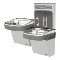
Visual representations of plumbing connections for versatile bi-level units.

EZ Bi-Level Plumbing Diagrams

Standard Pressurized Plumbing Diagram

Standard plumbing schematic for pressurized EZ bi-level coolers.

Plumbing Diagram with Filter and Bottle Filler Addition

Plumbing layout after adding a filter and bottle filler water line.

Wiring Diagrams and Components

Bubbler Assembly Detail

Close-up view and notes for the bubbler assembly components.

115V Non-Refrigerated Wiring Diagram

Electrical wiring schematic for 115V non-refrigerated models.

115V Refrigerated Wiring Diagram

Electrical wiring schematic for 115V refrigerated models.

Connection and Filter Details

Quick Connect Fittings Operation

Instructions on how to connect and disconnect tubing using quick fittings.

WATERSENTRY® PLUS Filter Details

Information and part details for the WATERSENTRY® PLUS filter system.

Parts Lists and Information

General Replacement Parts List

Comprehensive list of replacement parts for various cooler and filler components.

Bottle Filler Replacement Kits

Specific kits available for replacing bottle filler components.

Related product manuals