Do you have a question about the Elkay EZWSRK and is the answer not in the manual?
Specifies indoor use and requirement for authorized service personnel for all tasks.
Warns about electrical grounding issues causing electrolysis and recommends GFCI protection.
Lists essential tools needed for installation that are not supplied with the unit.
Advises installers to read instructions carefully, check compliance with codes, and leave instructions with the unit.
Details steps for removing panels, disconnecting water, and preparing the cooler for installation.
Provides instructions for assembling and mounting the filter head and filter assembly.
Outlines the procedure for pressurizing the water system, including connecting filter outlets and tubing.
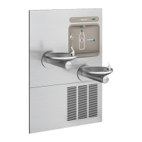
Describes modifications for standard and versatile Bi-Level models to integrate the filter.
Illustrates the plumbing for standard EZ non-pressurized configurations.
Shows plumbing changes after pressurization modifications for EZ units.
Depicts the standard pressurized plumbing setup for Bi-Level models.
Illustrates plumbing for Bi-Level models after adding the bottle filler water line.
Plumbing diagram for EZ non-pressurized models ending in 1, 1A, 2, or 3.
Plumbing diagram showing pressurization mods for EZ models ending in 1, 1A, 2, or 3.
Standard pressurized plumbing for Bi-Level models.
Plumbing for Bi-Level models with bottle filler water line addition.
Plumbing diagram for EZ non-pressurized configuration.
Shows EZ plumbing after filter installation and pressurization modifications.
Standard pressurized plumbing for Bi-Level models.
Plumbing for Bi-Level models with filter and bottle filler water line addition.
Plumbing diagram for EZ non-pressurized models ending in 1, 1A, 2, or 3.
Shows EZ plumbing after filter install and pressurization for models ending in 1, 1A, 2, 3.
Standard pressurized plumbing for Bi-Level models.
Plumbing for Bi-Level models with filter and bottle filler water line addition.
Instructions for removing the basin assembly from the unit.
Details preparation, reassembly, and specific instructions for different model types.
Electrical wiring diagram for the 115V bottle filler unit.
Wiring diagram for the non-refrigerated side of the unit.
Wiring diagram for the refrigerated side of the unit.
Guides on installing the mounting plate, positioning the unit, and securing it.
Details connecting water lines, installing the filter, power connection, leak checks, and final testing.
Provides steps to modify wiring on non-refrigerated units for bi-level coolers when the counter advances continuously.
Instructions to verify software version and access programming buttons.
Procedures to reset the filter monitor and bottle count.
Guides on setting IR sensor range, unit type (refrigerated/non-refrigerated), and filter capacity.
Shows primary and alternate outlet locations for standard rough-ins.
Illustrates primary and alternate outlet locations for reverse rough-ins.
Lists parts for the Watersentry Plus filter assembly, including part numbers.
Catalog of available replacement part kits with their descriptions and part numbers.
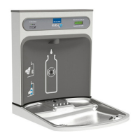
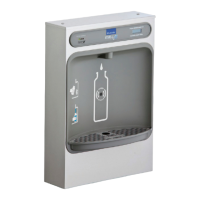
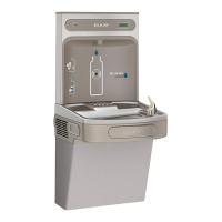
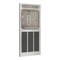
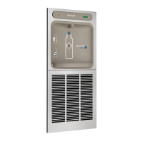
This manual describes the Elkay ezH2O® Retro-Fit Bottle Filling Unit, models EZWSRK and LZWSRK, designed for indoor applications. It provides comprehensive instructions for installation, use, and maintenance.
The Elkay ezH2O® Retro-Fit Bottle Filling Unit is designed to convert existing Elkay water coolers into bottle filling stations. Its primary function is to provide a convenient and hygienic way to refill water bottles, reducing the need for single-use plastic bottles. The unit integrates with the existing water cooler plumbing and electrical system, offering filtered water dispensing with an electronic sensor for touchless operation. It includes a bottle counter display and filter status indicator to inform users about usage and maintenance needs.
General:
Filter (EWF3000 WaterSentry® Plus Filter):
Dimensions (Standard Rough-In for Left-Hand High, Bottle Filler Low Models):
Dimensions (Alternate Rough-In for Right-Hand High, Bottle Filler Low Models):
Dimensions (Alternate Rough-In for Right-Hand High, Bottle Filler High Models):
Dimensions (Alternate Rough-In for Left-Hand High, Bottle Filler High Models):
Touchless Dispensing:
Bottle Counter:
Filter Status Indicator:
Unit Type Settings:
Programming Button:
Filter Replacement:
Wiring Modification for Bi-Level Coolers:
Troubleshooting:
General Maintenance:
| Brand | Elkay |
|---|---|
| Model | EZWSRK |
| Category | Water System |
| Language | English |