Page 298674C (Rev. E - 12/12)
LZWSR*1B
WALL
LEFT SIDE
EZH20 RETRO-FIT BOTTLE
FILLER
BASIN HOLE TEMPLATE
1 1/8"
1 3/4"
1/2"O
PILOT
HOLE
1-3/8"O
PUNCHE D
HOLE
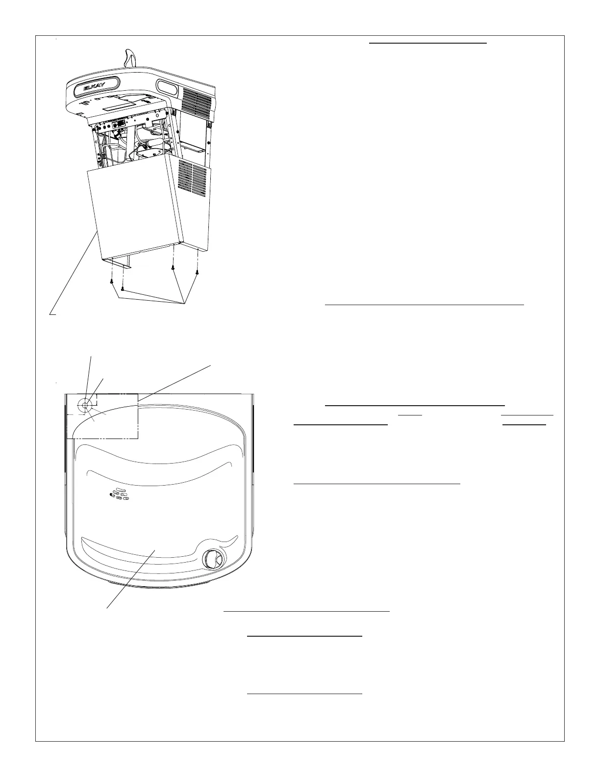
Fig. 2
WATER COOLER PREPARATION
1) Remove lower front panel of watercooler by removing the four (4) screws from
the bottom of cooler. (See FIG. 1) NOTE: For Two Level Models the Bottle Filling
Unit should be mounted to the higher unit. Both lower front panels and basin
assemblies will need to be removed.
1a) For units with model no’s. ending with 1, 1A, 2 or 3 these units will need to
be removed from the wall in order to remove the basin assembly(s).
2) Power OFF circuit that the water cooler is connected to by switching the
circuit breaker to the “OFF” position or by removing the fuse to the circuit.
Remove the water cooler plug from the outlet and shut off water supply.
3) Cut out the Drain Mat template located on the last page of the manual and
place the template on rear left side of the EZ cooler basin.
4) Locate 1-3/8” diameter hole on left side of the template (See FIG. 2). Mark
center of hole on basin with pencil.
5) Remove Basin Assembly by loosening four (4) screws two on each side of
cooler as shown in Fig. 5. Disconnect water line “A” from bubbler at the
evaporator tank (See Fig. 3). NOTE: When disconnecting water lines use a
container to catch any water running out of the lines. Disconnect basin
assembly from drain trap. Lift basin assembly straight up to remove, and
disconnect two wires from push bar switches. (Note: This will allow easier
assembly of water filter to unit and pressurization of the unit.)
5a) For units referenced in step “1a”. Remove Basin Assembly by loosening
four (4) screws two on each side of cooler as shown in Fig. 5. Remove 2 screws
from top back of unit to remove the “L” bracket. Remove 1 screw from left side of
cross brace in front of unit that retains the drain support. Disconnect water line
“A” from regulator at the evaporator tank (See Fig. 3B). NOTE: When disconnect-
ing water lines use a container to catch any water running out of the lines.
Disconnect basin assembly from drain trap. Lift basin assembly straight up to
remove, and disconnect two wires from push bar switches.
(Note: This
will allow easier assembly of water filter to unit and
pressurization of the unit.)
EWF3000 WATERSENTRY PLUS FILTER INSTALLATION
NOTICE: Do not use with water that is microbiologically unsafe or of
unknown quality without adequate disinfection before or after the system.
1) These filter kits must be installed in compliance with all state and local laws
and regulations governing the installation and use of this product. Maximum
inlet water temperature 100°F (38°C).
2) See filter instructions for filter assembly. Insert 3/8” elbow fitting into the
inlet side of filter head, insert 1/4” polytube or 1/4” x 90° elbow into outlet side
of filter head prior to mounting the filter head assembly into the cooler.
3) Mount filter head as shown in Fig. 6, using the filter mounting bracket and
screws supplied. For Two-Level units the filter must be mounted to the L.H.
non-refrigerated unit at the same location as shown in Fig. 6.
PRESSURIZATION OF WATER SYSTEM
NOTE: This proceedure MUST be performed on ALL SINGLE
EZ WATER COOLERS or the bottle filling unit WILL NOT
perform properly!
1) Remove water inlet (B) and outlet (C) from solenoid valve (See Fig. 3 or 3B).
NOTE: When disconnecting water lines use a container to catch any water
running out of the lines.
2) CAUTION: If supply pressure will ever exceed 100 psi, install a pressure
regulator to limit the inlet pressure to the filter to 100 psi or below.
DO NOT ATTACH HOT WATER LINE TO FILTER. To make connections on the
filter head, loosen locknut. Push the tube end past both o-rings to a positive
stop in the filter head recess - approx. 1", locknut may have to be backed out a
little more. Screw the locknut hand tight to seal (See Fig. 7). Ends of tubing
must be cut square and free of burrs and sharp ends that could cut or nick the
o-rings.
3) Connect the outlet of the filter to the inlet of the evaporator using the 1/4"
O.D. poly tubing and 1/4" union supplied (See Fig. 4 or 4B).
4) Cut a 12” long piece of poly tube (be sure to insulate poly tube with supplied
insulation tubing) and insert one end into the outlet side of the evaporator “D”
(See Fig. 4 or 4B), connect Tee to other end of tube.
5) Cut a 12” long piece of poly tube (be sure to insulate poly tube with supplied
insulation tubing) and insert into the Tee and the other end into the inlet side of
the solenoid valve “E” (See fig. 4 or 4B).
Fig. 1
LOWER COVER
SCREWS
PAPER
TEMPLATE
1-3/8” DIA. HOLE
1/2” DIA. HOLE
EZ BASIN
TWO-LEVEL MODIFICATION OF WATER SYSTEM
NOTE: Two-Level water systems are already plumbed for pressurization.
STANDARD TWO-LEVEL MODELS
Follow instruction 2 thru 4 under “Pressurization of water system” to attach filter to water system. The non-refrigerated side must be removed from the wall
in order to remove the basin assy. and install the filter head assy.
1) Remove the Two-Level Cover Plate from the right hand side of the non-refrigerated unit in order to access the rear Basin Assy. screw.
2) Cut poly tube “H” between the existing tee and the solenoid valve of the L.H. unit.
3) Insert supplied 1/4” Tee in water line “H” where it was just cut (See Fig. 4A).
TWO-LEVEL REVERSED MODELS
Follow instruction 2 thru 4 under “Pressurization of water system” to attach filter to water system. The non refrigerated side must be removed from the wall in order to
remove the basin assy. and install the filter head assy.
1) Remove the Bi-Level Cover Plate from the left hand side of the refrigerated unit in order to access the rear Basin Assy. screw (See Fig 5).
2) Cut poly tube “H” approximately 3” from the left side of the existing tee.
3) Insert supplied 1/4” tee in water line “H” where it was just cut.
 Loading...