Art.-Nr./Art. No./Réf./N° art/N° art.: 9010008B01M Version/Version/Version/Versione/Versión: 1.3 Datum/Date/Date/Data/Fecha: 29.08.2017 5/18
* When selecting the logic operator, ensure that the resulting function fulfils the
specified safety function and corresponds to the specified properties.
* The control output is switched on after initialization.
No input is assigned when selecting BTR, error or safety output. The outputs’
switch-on/switch-off delay time of between 0.0 s and 99.9 s can be set in
0.1 second steps.
LED displays
Operating time
The operating time is the maximum time permitted on a sensor between actua-
tion of both sensor contacts.
With 2-hand operation, it is the maximum time permitted between actuation of
both sensors.
Safe condition
The safety outputs are opened or with high resistance.
Hazardous condition
The safety outputs are closed or with low resistance.
8 Technical specifications
See "Technical specifications" from page 15.
9 Installation
- Installation of the safety control unit is only permitted in a voltage-free state.
- Ensure that the prescribed fuses (see "Technical specifications") are used.
- Snap the safety control unit onto a mounting rail (DIN EN 60715 TH35) in the
switch cabinet. The safety control unit is fixed.
- Connect the safety control unit.
The pluggable terminal blocks can be coded by means of pins, the sockets
in the device are inversely coded by means of coding tabs.
- If the safety input remains free:
Ensure that the contact makers of this safety input are bridged.
10 Electrical connection
- Electrical connection is only permitted in a voltage-free state.
- Make sure that the details described in the technical specifications are al-
ways complied with.
- Measures to improve the equipment’s immunity to interference from line-
conducted and radiated high frequency interference are to be taken
(DIN EN 60204-1:2007-06, para 4.4.2).
When connecting the sensor, the sensor power supply voltage (+) and (-)
terminals identified in the technical specifications are to be used.
Terminal connections
11 Commissioning
In random order:
- Damp safety sensors.
- Apply operating voltage.
- Then actuate the start button if necessary.
The LEDs of the inputs and outputs used and the "Ready" LED light up.
The safety control unit is ready. The safety control unit switches through the
safety output.
Control outputs 1-4
Input Logic Switch-on/switch-off
delay in s
Safety input 1 AND t
ON
, s
___
t
OFF
, s
Safety input 2 OR
Safety input 3 NAND
Safety input 4 NOR
XOR
XNOR
NOT
BTR*
ERROR
as for safety output 1
as for safety output 2
as for safety output 3
as for safety output 4
Danger
Danger of electrocution!
Ensure that the safety control unit is installed and put into
operation only by specially trained, authorized personnel.
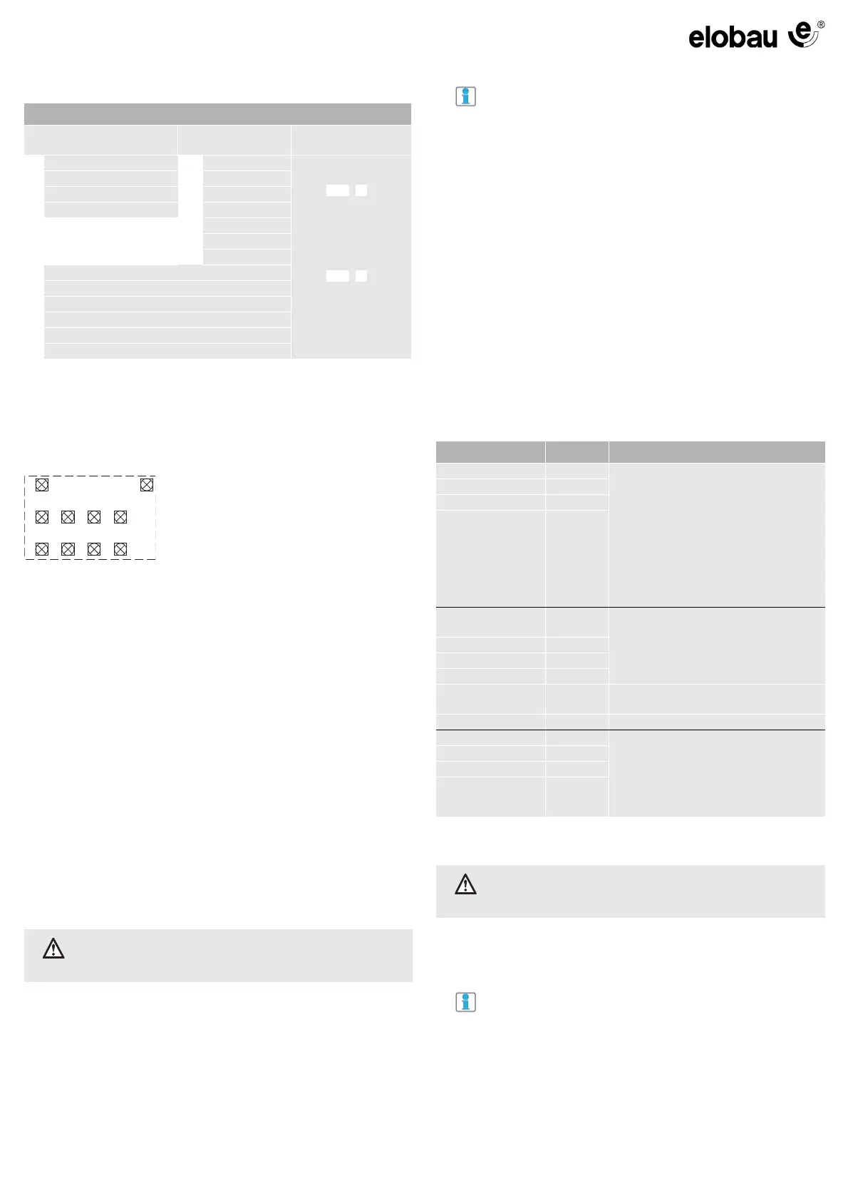
LED 1 Operability ("Ready")
LED 2 Fault ("Error")
LED 3 Safety input 1 ("I 1")
LED 4 Safety input 2 ("I 2")
LED 5 Safety input 3 ("I 3")
LED 6 Safety input 4 ("I 4")
LED 7 Safety output 1 ("O 1")
LED 8 Safety output 2 ("O 2")
LED 9 Safety output 3 ("O 3")
LED 10 Safety output 4 ("O 4")
Accessories
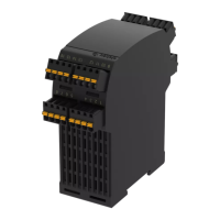
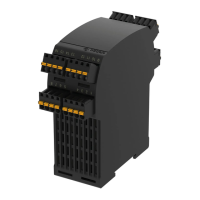
Spring terminals are supplied as standard (order number
878598).
Optional screw terminals (order number 878719) and dou-
ble terminals (order number 878717) are available from
elobau.
A corresponding coding tab set is available from elobau un-
der order number 350SAE001.
Components Terminals Explanation
Safety input 1 5-8 Depending on configuration, the inputs at
terminals 5, 13, 21, 29 (+) or (-) are read-
only.
Connection options:
- Sensors with 2-NO system
- Sensors with NO/NC System
- Emergency stop push button
- 2-hand control
- Light grid (OSSD)
- Photoelectric sensor (OSSD)
Safety input 2 13-16
Safety input 3 21-24
Safety input 4 29-32
Safety output 1 1, 25
Switching dependent on
- Safety input 1-4
- Logic
- Switch-on/switch-off delay (optional)
- Contactor/start inputs (optional)
Safety output 2 2, 26
Safety output 3 3, 27
Safety output 4 4, 28
External contactor/
Start 1-2
11, 12 External contactor and/or start button
(automatic, manual or monitored)
Operating voltage 9, 10
Control output 1 17 Not suitable for safety functions!
Switching dependent on
- Safety input 1-4
- Logic
- Switch-on/switch-off delay times
(optional)
Control output 2 18
Control output 3 19
Control output 4 20
Danger
Danger of electrocution!
Ensure that the safety control unit is installed and put into
operation only by specially trained, authorized personnel.
NOTE
Make sure that no external voltage is applied to the safety
inputs when the operating voltage is applied (e.g. by devic-
es with OSSD outputs).
 Loading...