Проверил: Р.Ч./18.03.2015г.
4
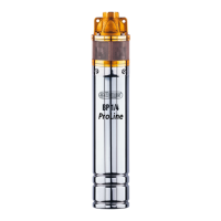
The engine of the pump and the pump case are separate units connected by coupling and by
4 M8 bolts.
Corrosion-resisting materials are used for the structure. The case and the shafts are made of
INOX chromium steel; the other parts of the pump are made of stable corrosion-resisting
plastics, while of bronze for BP ¼. The part of the power cable next to the pump is
protected by an INOX head-plate.
The pump runs in a vertical position, the electric motor is below, the pump is above, this
way the motor’s water-cooling is ensured during operation. The pump’s discharge inlet is on
the top (C 5/4” internal thread). The pump rotates to the left seen from the discharge flange.
4.) START-UP AND OPERATION
4.1 Mechanical installation
During installation ensure that the pump is put to its final place and in the case of a drilled
well, the inner diameter of the well tube should be minimum 110mm. The pump must not be
installed to the bottom of the well, because it becomes useless from the sand and mud
entering the pump.
It is advisable to place the pump at a minimum of 50 cm from the filter (perforation) of the
well. Before the pump is connected to the penstock, seal it properly. It is useful to install a
closing and control cock onto the penstock in the immediate proximity of the well. The
outlet cable is fixed to the penstock by plastic clamps. (In the case of flexible or PVC
penstock the cable should be fixed to the inlet rope). Supporting clips should be placed onto
the penstock which supports the penstock and the water column within the penstock against
the walls of the well or against the ground. The pump is lowered into the well by the help of
a lowering-lifting steel rope bound into the 2 bore-holes of 10mm diameter of the discharge
flange.
The height of the water column loading the pump can be maximum 10m.
It is forbidden to use the outlet cable for the lifting or moving of the pump during shipping
or installation.
4.2 Electric connection
The machine can only be connected to a network equipped by a single-phase earth wire. The
power connection must be indoor and protected from dripping and slashing water. Choose a
place of connection which is accessible easily.
Before the plug socket install a cutout of 10A rated current marked by G or B as short-
circuit protection; the cutout should be provided by the user. In order to ensure protection
against contact, a sensible leak current protective switch (Fi relay 30mA DIN
VDE0110T739) will be installed.
The overheating protection of the pump motor is ensured by the overtemperature relay
mounted into the coil end which stops the motor’s operation in the case of 130°C coil
temperature and signals the breakdown. Attention: once the temperature of the coil end
decreases, the motor restarts automatically.
 Loading...