• Communication with internal UPS module is lost.
• Temperature within the actuator is too high.
• The battery for the internal UPS needs service or the battery state of charge
is below the set minimum value.
•
The failsafe state must be reset from the IAS.
If the hand wheel is turned, the actuator goes to service state. This state must be
reset from the IAS to resume the actuator to normal state after manual operation
is finished.
For more details, please refer to the System Integrators Manual.
The service state is activated remotely via the IAS, or locally by operating the
hand wheel. The service state makes the actuator accessible for inspection or
service and prohibits the failsafe state if any failsafe criteria is fulfilled. Thus, the
service state also facilitates manual operation.
Once the service state is no longer required, it is cleared remotely via the IAS.
The actuator then resumes normal or failsafe state, whichever that was active
prior to service.
B.7.iii.
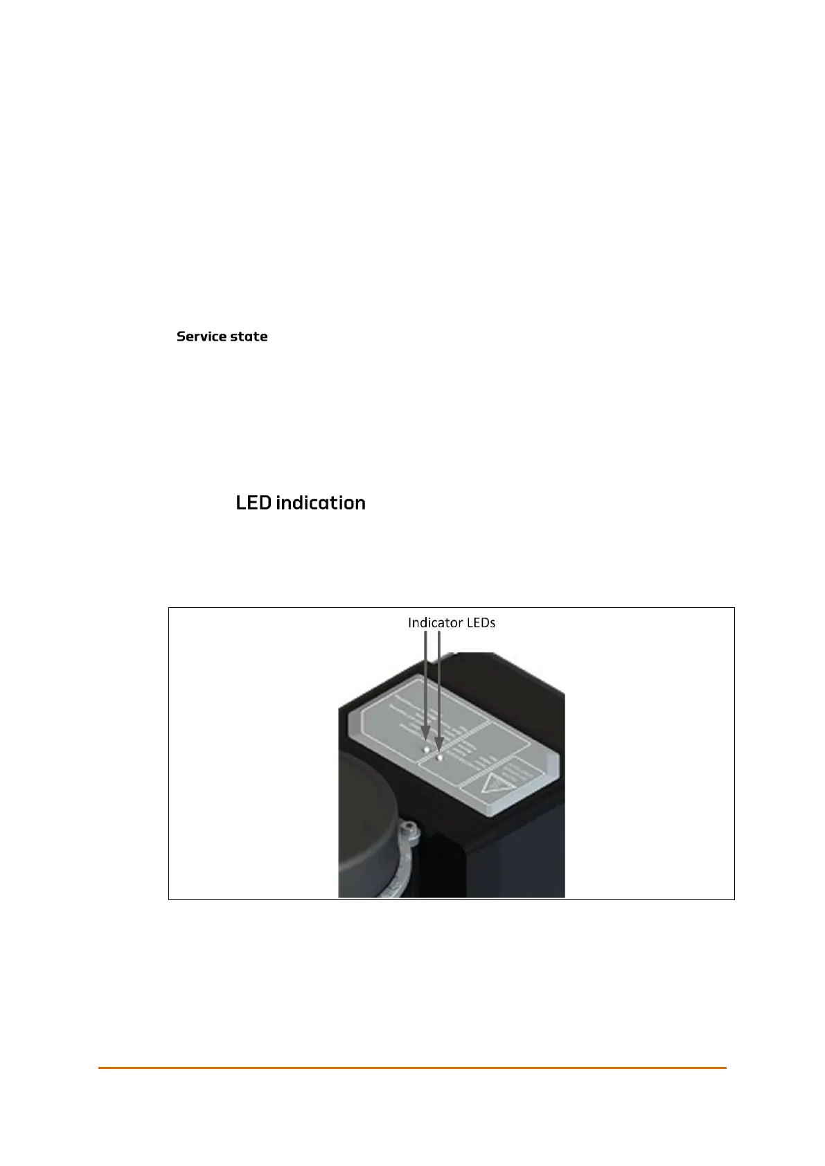
The indicator LEDs are positioned at the top of the UPS unit. The label describes
the LED indications. Table 8-21 shows how the battery condition and the actuator
states are indicated by the two LEDs on the actuator.
Figure 46: QT250 and QT800 –indicator LEDs
 Loading...
