- Is trigged by a positive edge followed by an active signal for at least 100
Ms.
- The actuator stops and sets ALARM status if OPEN signal is activated
during a CLOSE command, or CLOSE signal is activated during an OPEN
command.
• CLOSED signal and OPEN signal (outputs)
• ALARM signal (output)
- Activated if GENERAL ALARM is triggered.
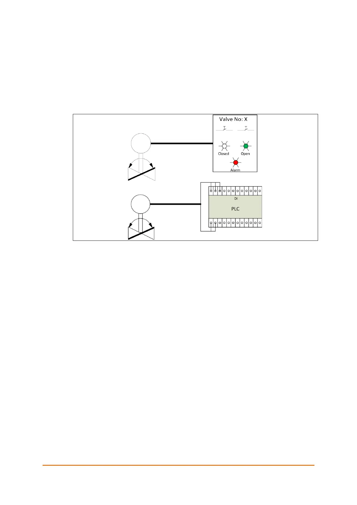
Figure 35: Digital control using buttons and lamps or PLC
As shown on the illustration above, actuators with digital interface can be
controlled directly from a conventional panel with buttons/ switches and
indicator lamps. Alternatively, it can be controlled from a controller with Digital
inputs and outputs. This allows extended functionality in terms of automatic
control and visual user interface on display.
In case both the Close and Open signals are active simultaneously, the actuator
opens. Both input and output signals can use pulses of minimum 100ms length
or constant signals.
The outputs provide feedback of the actuator’s status, such as Closed, Open
and/or Alarm.
The following failure scenarios trigger an alarm:
• Manual emergency operation
• Valve position out of defined operation area
• Valve blocked
• High temperature
• Power failure (if alarm output is inverted)
• 4 – 20 mA control signal is lost
 Loading...
