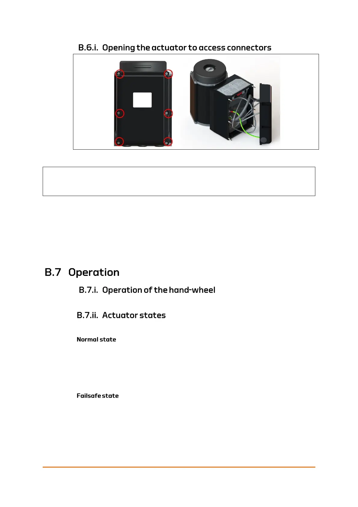
Figure 45: QT250 – opening the failsafe actuator
Remove the six hexagon socket cap nuts holding the interface to the actuator.
The nuts are circled in red in the illustration. Remove the nuts by turning them
counterclockwise. Place the nuts in a secure location.
Required equipment:
• 4mm Hexagon Key
See Manual operation on page 43.
The Failsafe actuator has three states: Normal, failsafe and service.
This is the state the actuator is in when everything is good. If failsafe state or
service state has been activated, normal state is only resumed if failsafe or
service is cleared from the IAS.
In normal state, the UPS operates in normal mode. Normal mode for UPS means
charging (when the actuator is idle) or standby.
The actuator moves to the pre-configured failsafe position in the following cases.
• The power is lost.
• The communication signal is lost.
The actuator may also be configured to move to the pre-configured failsafe
position for internal errors in the actuator, such as:
Caution! The interface and failsafe module are loose when the nuts are removed.
Make sure not to drop the interface, or to let it hang by the cables.
 Loading...
