• Note: We recommend connecting the cables with a fork Faston of a size suited to the stud screws, and inserting
it between the head of the screw and the washer, arranging the cables so as to avoid contact between adjacent
Fastons.
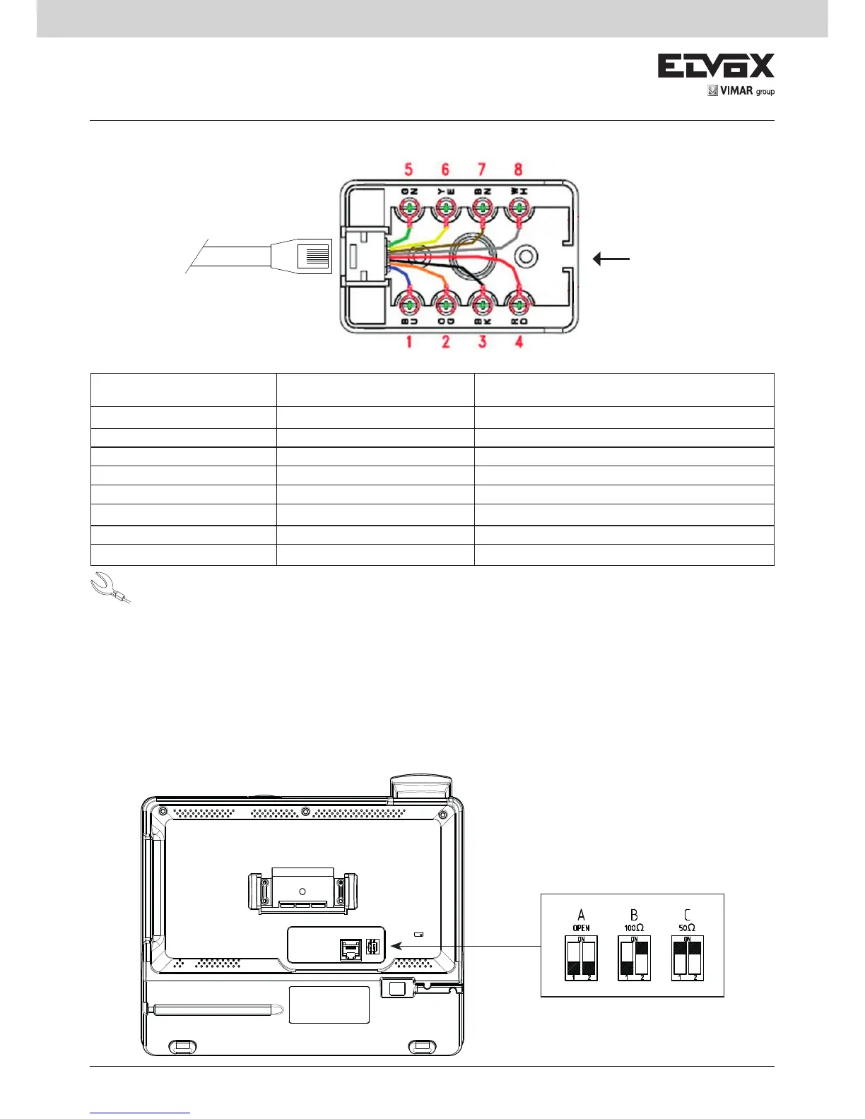
Connection correspondence table: interconnecting stud - Due Fili system
Connection box terminals Connection box wire colour Due Fili audio / video door entry system
BU 1
•
Blue
1 (Due Fili Bus)
OG 2
•
Orange
2 (Due Fili Bus)
BK 3
•
Black
from power supply unit 6923 terminal -
RD 4
•
Red
from power supply unit 6923 terminal +I
GN 5
•
Green
-
YE 6
•
Yellow
-
BN 7
•
Brown
-
WH 8
•
White
-
Access hole for Due Fili
Bus and power supply
cables
to switchboard
Video Termination
Select DIP switch to terminate the video signal
A) if the BUS cable enters terminals BU (1), OG (2) of the switchboard interconnecting stud and continues to another indoor
unit.
B) when a BUS cable with typical impedance of 100 Ohm (Elvox cable 732I or 732H) enters terminals BU (1), OG (2) of the
interconnecting stud and the riser stops in the switchboard.
C) when a BUS cable with typical impedance of 50 Ohm (Cat. 5 or Cat. 6 twisted pair cable) enters terminals BU (1), OG (2) of
the interconnecting stud and the riser stops in the switchboard.