16
9101112
Italiano English Français
ASSEMBLAGGIO ASSEMBLY ASSEMBLAGE
MONTAGGIO MANUBRIO (STEGOLE)
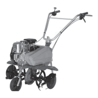
Tipo A (Fig.9)
Montare il manubrio A sul piantone B, fissarlo nel foro C con
vite D, rondelle E e dado F (vedi Fig.9).
Questo manubrio può essere regolato solo in verticale
utilizzando i tre fori G:
utilizzare la vite H, la rondella I e il pomello L (vedi Fig.9) per
fissare il manubrio.
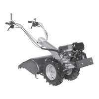
Tipo B (Fig.10)
Montare la ghiera Q, il manubrio R e la rondella S sulla vite del
piantone U. Fissare il manubrio con il pomello T.
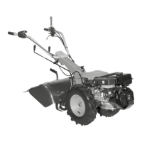
Questo manubrio può essere regolato sia in orizzontale che
in verticale (Fig.11):
Svitare il pomello T, regolare il manubrio per trovare una
posizione comoda di lavoro e serrare di nuovo.
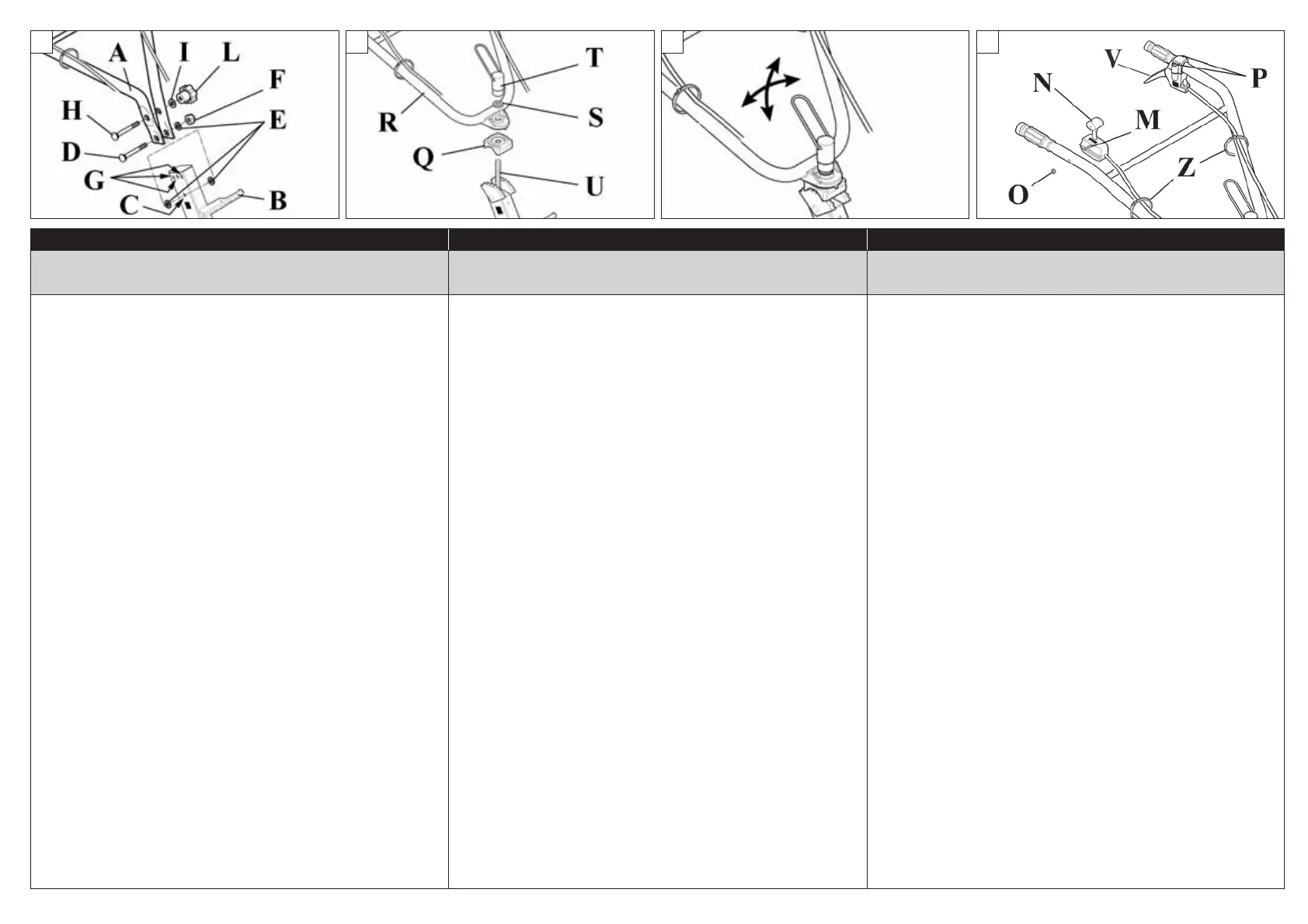
MONTAGGIO ACCELERATORE E LEVA
Fissare al manubrio l’acceleratore / interruttore (N, Fig.12)
utilizzando la vite M e il dado O.
La leva (V, Fig.12) è già inserita sul manubrio, è solo necessario
serrare le viti P.
Fissare il cavo dell’acceleratore e il cavo della leva utilizzando
le due fascette come in Fig.12.
FITTING THE HANDLEBAR
Type A (Fig.9)
Fit handlebar A onto steering column B, secure it in hole C
using bolt D, washer E and nut F (see Fig.9).
This handlebar can only be adjusted vertically, using the
three holes G:
use bolt H, washer I and knob L (see Fig.9) to lock the
handlebar in place.
Type B (Fig.10)
Fit ring nut Q, handlebar R and washer S onto the bolt of
steering column U. Lock the handlebar in position using
knob T.
This handlebar can be adjusted both horizontally and
vertically (Fig.11):
Unscrew knob T, adjust the handlebar to find a comfortable
operating position, then retighten the knob.
FITTING THE THROTTLE AND LEVER
Secure the throttle / switch (N, Fig.12) using bolt M and nut O.
The lever (V, Fig.12) is already fitted to the handlebar, you
simply need to tighten the screws P.
Secure the throttle cable and the lever cable using the two
clips as shown in Fig.12.
MONTAGE DU GUIDON (MANCHERONS)
Type A (Fig.9)
Monter le guidon A sur la colonne B, le fixer dans l'orifice C
avec la vis D, les rondelles E et l'écrou F (voir Fig.9).
Il est possible de régler le guidon uniquement sur la position
verticale en utilisant les trois orifices G :
utiliser la vis H, la rondelle I et le pommeau L (voir Fig.9) pour
fixer le guidon.
Type B (Fig.10)
Monter la bague Q, le guidon R et la rondelle S sur la vis de la
colonne U. Fixer le guidon sur le pommeau T.
Il est possible de régler le guidon à l'horizontale et à la
verticale (Fig.11) :
Dévisser le pommeau T, régler le guidon pour trouver une
position confortable pour le travail et serrer à nouveau.
MONTAGE DE L'ACCÉLÉRATEUR ET DU LEVIER
Fixer l’accélérateur / interrupteur (N, Fig.12) sur le guidon à
l'aide de la vis M et de l'écrou O.
Le levier (V, Fig.12) est déjà installé sur le guidon, il suffit de
serrer les vis P.
Fixer le câble de l’accélérateur et le câble du levier à l'aide des
deux colliers comme le montre la Fig.12.
 Loading...