26
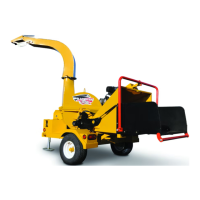
3. DeectorPosition:
Each discharge hood is equipped with a de-
ector on the end to place the chips exactly
where desired. The deector support bracket
is designed with slots to position the deector
where desired. Place in the appropriate slot.
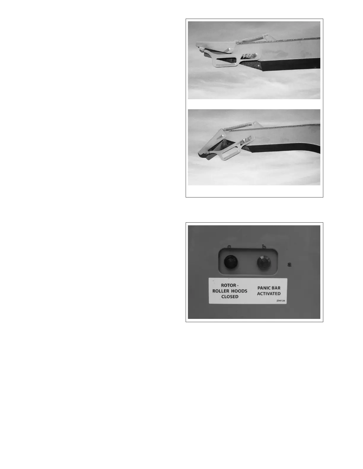
4. Control Panel:
a. Controller:
Review the controller operator's manual
provided with the machine for detailed
operating instructions. This panel displays
the parameters monitored by the control-
ler. Depress the title works on the front
of the panel to select the display for the
engine oil life, machine hours and rotor
RPM.
b. Panic Bar Activated:
This light is illuminated when the "Panic
Bar" is activated and goes out when it is
reset.
c. Roller - Roller Hood Closed:
This light is illuminated when both the roller
and rotor hood are closed and goes out
when the hoods are opened.
Far
Close
Fig. 4 DEFLECTOR POSITION
Fig. 5 CONTROLLER
a
b
c