10
For more information, refer to Celerra Tools on http://Powerlink.EMC.com
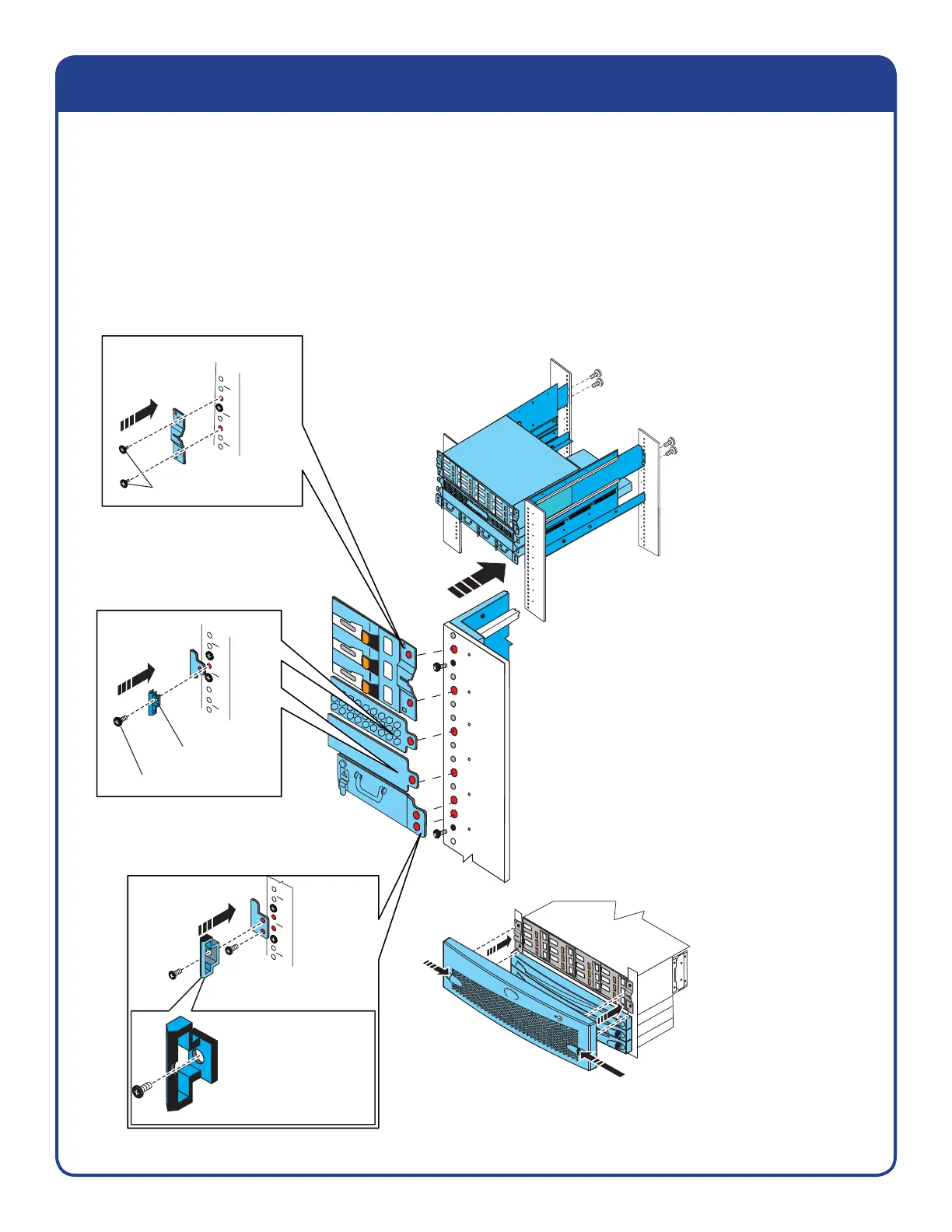
Components, latches, and bezels
1. Install the bottom component first
( 1 2 3 4 ). Ensure that each component
is secure before you install the next
component above it.
2. Snap on the bezels.
Disk processor enclosure (DPE)
2U latch and 2 screws each side
2 screws each side
Right front side
CNS-001430
Rail catch
1 screw each side
Control Station (CS) and
standby power supply (SPS)
1U latch each and
1 screw each, each side
Right front side
Press
Snap on bezels
Press to install the bezel,
then release.
The indentation goes
toward the inside of
the rack.
Install the lower
screw first with 2 screws
on each side.
Right front side
Inside
Blade enclosure
1U latch, 2 screws each side
Inside
1. Install the bottom component fi rst, and continue to individually install each component.
2. Ensure that each component and all screws are secure as the component is installed;
also install the latches as you install each component.
3. After all of the components and latches are in place, snap on the bezels.