16 VNX5500 Hardware Information Guide
System component description
Table 3 describes the Block and File (Unified) VNX5500 platform disk processor and
2.5-inch disk drive status LEDs.
Control Station front view
On the front, the Block and File (Unified) VNX5500 platform Control Station includes the
following:
◆ DVD-ROM drive
◆ USB 2.0 connector (not used)
◆ Control switch and status LEDs
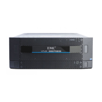
Figure 6 shows the orientation of these components.
Figure 6 VNX5500 Control Station (front view)
Table 3 VNX5500 platform 3U, 25 DPE and disk drive status LEDs
LED Color State Description
DPE fault (location 2) Amber On Fault has occurred
DPE power (location 3) Blue On Powering and powered up
— Off Powered down
Disk drive fault (location 4) Amber On Fault has occurred
— Off No fault has occurred
Disk drive on/activity
(location 5)
Blue On Powering and powered up
Blinking Disk drive activity
1 DVD-ROM drive 3 USB 2.0 connector (not used)
2 Control Station switch and status LEDs (for
a closer view, see Figure 6)
DVD
1
2
3
CNS-001740

 Loading...