76 VNX5500 Hardware Information Guide
Disk-array enclosure
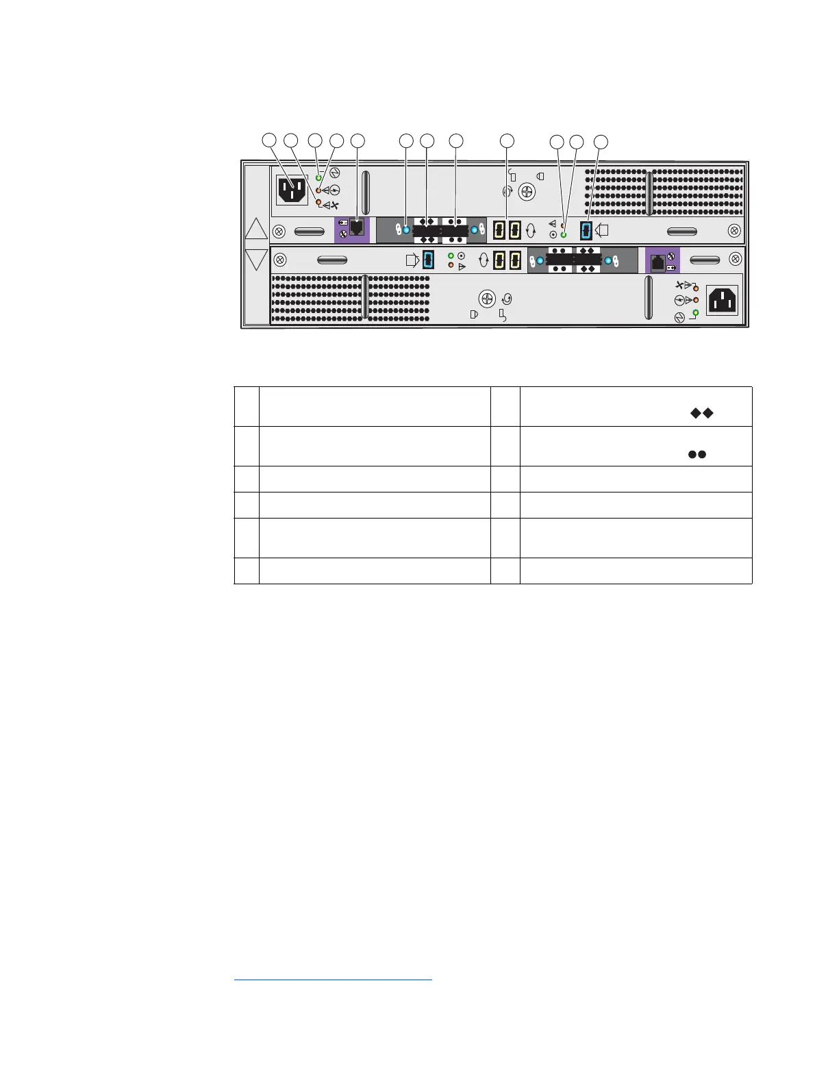
Figure 65 shows an example of the rear view of a 3U, 15 (3.5-inch) DAE.
Figure 65 3U, 15 (3.5-inch) DAE with two LCCs and two power supply/cooling modules (rear view)
As shown in the preceding figure (Figure 65), an enclosure ID
1
indicator is located on each
LCC. Each LCC also includes a bus (back-end port) identification indicator. The SP
initializes the bus ID when the operating system is loaded.
1 LCC B AC power supply (power in) recessed
connector (plug)
7 LCC B SAS connector (output); labeled
with a double diamond symbol
.
2 LCC B power supply fan fault LED (on,
amber)
8 LCC B SAS connector (input); labeled with
a double circle (or dot) symbol
.
3 LLC B power supply LED (on, green) 9 LCC B bus ID
4 LCC B power supply fault LED (on, amber) 10 LCC B bus LED (fault, amber)
5 LCC B management (RJ-12) connector to
SPS (not used)
11 LCC B bus LED (on, green)
6 LCC B SAS connector link LED 12 DAE enclosure ID or address
A
B
X4
6Gb SAS
X4
6Gb SAS
LCC B
LCC A
VNX-000100
2
4
1
567 9
10 11 12
8
3
1. The enclosure ID is sometimes referred to as the enclosure address (EA).
 Loading...


