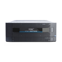
Disk-array enclosure
VNX5500 Hardware Information Guide 97
ICM
The 4U, 60 DAE external interfaces are made through the ICM. The ICM is the primary
interconnect management element.
The ICM is a plug-in module that includes a USB connector, RJ-12 management adapter,
Bus ID indicator, enclosure ID indicator, two input SAS connectors and two output SAS
connectors with corresponding LEDs indicating the link and activity of each SAS connector
for input and output to devices.
The ICM is hot-swapable. It has a built-in thumbscrew for ease of installation and removal.
As described previously, the ICMs in a 4U, 60 DAE connect to the SPE and other DAEs with
6-Gb/s SAS cables. The cables connect the ICMs in a system in a daisy-chain topology.
As shown in Figure 88 on page 97, an enclosure ID
1
indicator is located on each ICM. Each
ICM also includes a bus (back-end port) identification indicator. The SP initializes the bus
ID when the operating system is loaded.
Figure 88 Example of ICM connectors and LEDs (rear view)
1. The enclosure ID is sometimes referred to as the enclosure address (EA).
1 ICM USB connector 6 Four ICM SAS input/output connector LEDs
(bi-color blue/green)
2 ICM management (RJ-12) connector to SPS 7 Two ICM SAS output connectors; labeled
with a double diamond symbol
.
3 ICM bus ID indicator (yellowish green) 8 ICM thumbscrew
4 Two ICM bus ID LEDs (power, green; fault,
amber)
9 Two ICM SAS input connectors; labeled
with a double circle (or dot) symbol
.
5 ICM enclosure ID indicator (blue)
1
2
3
4
5
9
6
7
VNX-000629
8

 Loading...