88 VNX5700 Hardware Information Guide
Disk-array enclosure
Table 45 describes the 4U, 60 DAE status LEDs.
Rear view
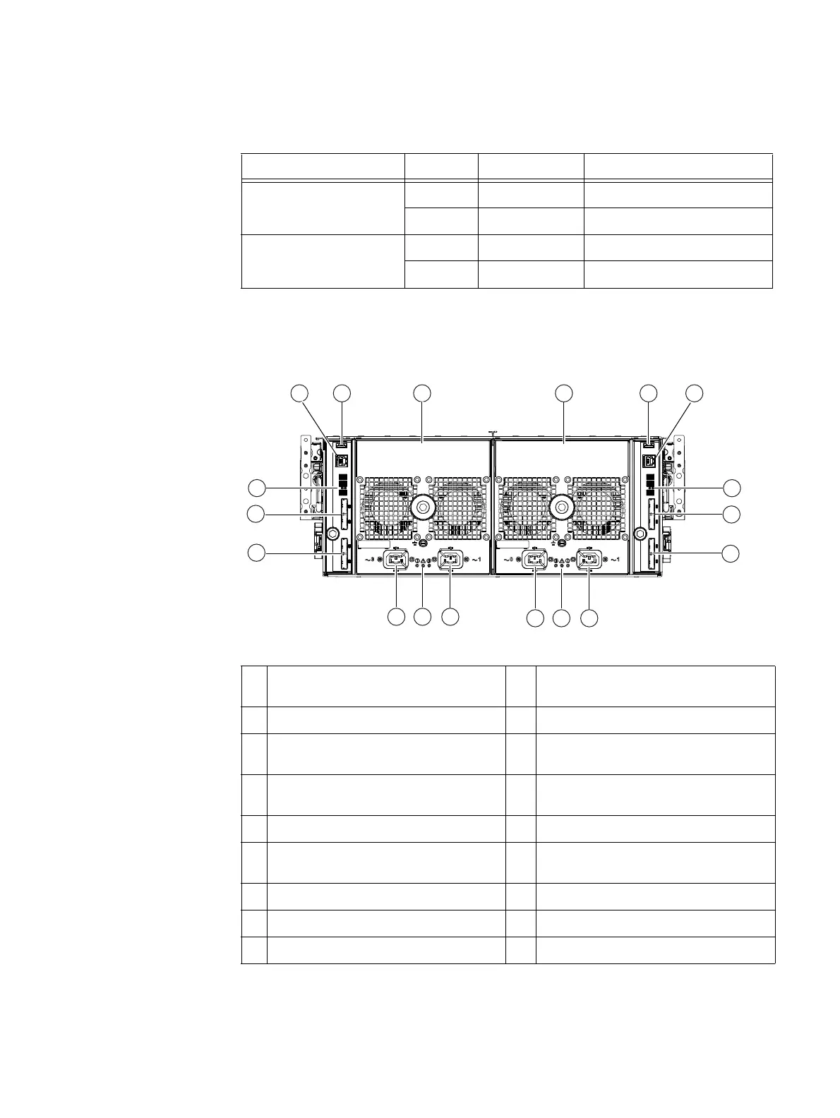
On the rear, viewing from left to right, a 4U, 60 (2.5- or 3.5-inch) DAE includes two 6 Gb/s
SAS ICMs (A and B) and two power supply modules (A and B) as shown in Figure 78.
Figure 78 Example of 4U, 60 DAE with two ICMs and two power supply/cooing modules (rear view)
Table 45 4U, 60 DAE status LEDs
LED Color State Description
DAE power Blue On Powering and powered up
— Off Powered down
DAE power fault Amber On Fault detected
— Off No fault detected
1 ICM A management (RJ-12) connector to
SPS
10 4U, 60 DAE B AC power supply power in
(recessed plug), labeled 1
2 ICM A USB connector 11 4U, 60 DAE B power and fault LEDs
3 4U, 60 DAE A AC power supply) 12 4U, 60 DAE B AC power supply power in
(recessed plug), labeled 0
4 4U, 60 DAE B AC power supply power in
(recessed plug)
13 4U, 60 DAE A AC power supply power in
(recessed plug), labeled 1
5 ICM B USB connector 14 4U, 60 DAE A power and fault LEDs
6 ICM B management (RJ-12) connector to
SPS
15 4U, 60 DAE A AC power supply power in
(recessed plug), labeled 0
7 4U, 60 DAE B bus ID and enclosure ID 16 ICM A SAS connector (output)
8 ICM B SAS connector (input)
1
1. The SAS connector (input) is labeled with a double circle (dot) symbol.
17 ICM A SAS connector (input)
9 ICM B SAS connector (output)
2
2. The SAS connector (output) is labeled with a double diamond symbol.
18 4U, 60 DAE A bus ID and enclosure ID
2 43 51
6
7
8
10
VNX-000627
1112
131415
18
16
9
17


 To Next Page