46 EMC VNX5300 Hardware Information Guide
Disk-array enclosure
Figure 37 LCC RJ-12 port
The cable connecting the LCC to the SPS is an RJ-12 to RJ-12. It has an RJ-12 adapter (LCC
side) on one end and a RJ-12 (SPS side) adapter on the other end.
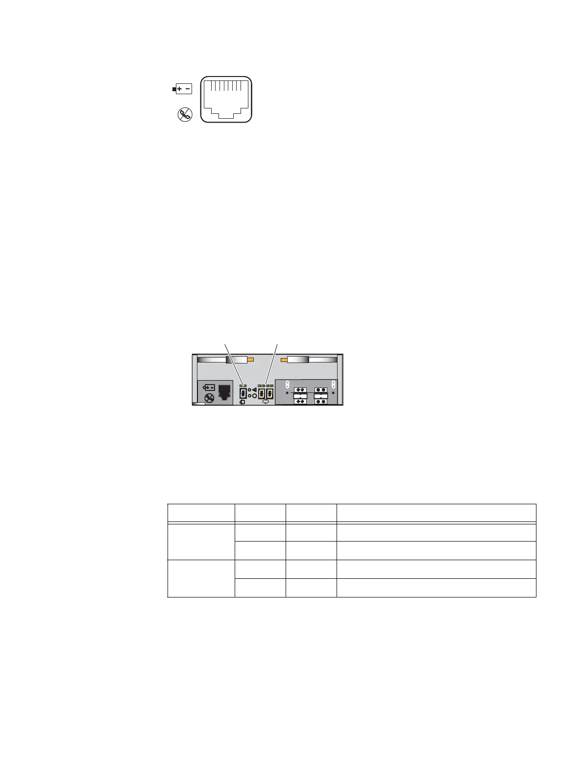
LCC enclosure ID (enclosure address) and bus ID
On the rear of the LCC (A and B), an LCC enclosure ID indicator is provided. This ID
indicator is a seven-segment LED display for displaying decimal numbers. The LCC
enclosure ID appears on both LCCs (A and B) which is the same ID number. The enclosure
ID is set at installation (Figure 38).
Each LCC includes a bus (loop) identification indicator. This indicator includes two
seven-segment LED displays for displaying decimal numbers. The SP initializes the bus ID
when the operating system is loaded (Figure 38).
Figure 38 Example of LCC B enclosure ID and bus ID
Table 25 describes the bus (loop) status LEDs.
VNX-000106
6 Gb
SAS
X4
#
X4
Bus (loop) ID
LCC enclosure ID
VNX-000277
Table 25 LCC bus (loop) status LEDs
Led Color State Description
Power fault Amber On Fault
— Off No fault or power off
Power on Green On Power on
—OffPower off
 Loading...

