PART NO. 37-7569
1504
1F83H-21NP (Non-Programmable)
Installation and Operating Instructions
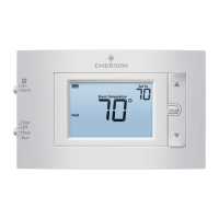
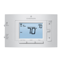
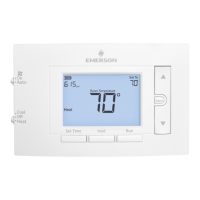
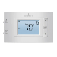
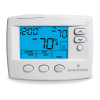
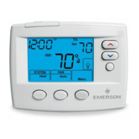
80 Series Heat Pump Thermostat
Battery Powered or Hardwired with Common
emersonthermostats.com
white-rodgers.com
Thermostat Applications
Maximum
Stages
Heat /Cool
Single Stage Compressor, Heat Pump
Systems (air source or geothermal) –
1 Stage Aux/Emergency Heat
2/1
Thermostat Installation
2-4
Wiring
2
Installer Menu
3-4
Using the Thermostat
5-6
Thermostat Overview
5
User Menu
6
Troubleshooting
7-8
Homeowner Help Line
8
INDEX
MERCURY NOTICE: This product does not contain
mercury. However, this product may replace a product
that contains mercury. Mercury and products containing
mercury must not be discarded in household trash.
Refer to www.thermostat-recycle.org for information
on disposing of products containing mercury.
Electrical Rating:
Battery Power ..................................... 20 to 30 VAC, NEC Class II, 50/60 Hz
Input-Hardwire .................................... 20 to 30 VAC, NEC Class II, 50/60 Hz
Terminal Load .......................................... 1.5 A per terminal, 2.5A maximum all terminals combined
Setpoint Range ........................................ 45° to 99° F (7° to 37° C)
Rated Dierentials (@ 6°F/ Hr): Fast Med Slow
Heat Pump (Heat)................................ 0.9°F 1.2°F 1.7°F
Heat Pump (Cool) ................................ 0.9°F 1.2°F 1.7°F
Auxiliary Heat ...................................... 0.5°F 0.75°F 1.9°F
Operating Ambient .................................. 32°F to +105°F (0° to +41°C)
Display Temperature Range ....................... 32°F to +99°F (0 to 37°C)
Operating Humidity ................................. 90% non-condensing maximum
Shipping Temperature Range ................... -20°F to + 150°F (-29° to +65°C)
Thermostat Dimensions ........................... 3-3/4” H x 6” W x 1-1/8” D
SPECIFICATIONS
Optional Accessory: Wall Cover-up Plate F61-2663, 6 3/4” W x 4 1/2” H
2
Terminal Designations Terminal Function
R
Power (24V)
O/B
Changeover Terminal-Energized in Cool (O) or Heat (B)
for Heat Pump or Damper Systems
Y
Heat and Cool Mode 1st Stage Compressor
G Fan Relay
E* Auxiliary only Heat Mode (Emergency Heat)
C
Common wire for 24V (optional with batteries)
L
Heat Pump malfunction / Diagnostic terminal
(input signal requires common)
W2* Heat Mode – 2nd stage
*Cut W2/E jumper when separate heat sources are used for W2 and E.
IMPORTANT: For Dual Fuel Heat Pump applications, be sure to turn on the Duel Fuel Logic option
(found in the Installer’s Menu)
WIRING
Refer to equipment manufacturer’s instructions for specic system wiring information. After
wiring, see INSTALLER MENU for proper thermostat conguration. Wiring table shown are
for typical systems and describe the thermostat terminal functions.
THERMOSTAT INSTALLATION
Precautions
• Do not exceed the specication ratings.
• All wiring must conform to local and national electrical codes and ordinances.
• This control is a precision instrument, and should be handled carefully. Rough handing or
distorting components could cause the control to malfunction.