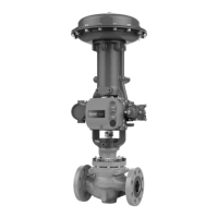
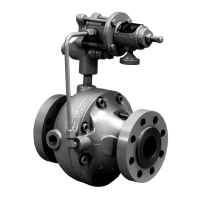
Do you have a question about the Emerson 3401 and is the answer not in the manual?
Explains the Commander SK as an open-loop vector AC variable speed inverter drive.
Explains the Commander SK as an open-loop vector AC variable speed inverter drive.
Procedure for saving user parameters to EEPROM, including conditions and commands.
Information on loading default parameter sets and their automatic saving to EEPROM.
Defines maximum allowed values for software variables like FREQ_MAX and RATED_CURRENT_MAX.
Describes the use of Pr x.00 (not Pr 0.00) for storing parameters and special codes.
Explains the reasons and methods for performing a drive reset.
Describes how drive parameters are stored via keypad and serial interface.
Describes how drive outputs and PID controllers function as sources.
Explains how drive inputs and other functions act as destinations for routing.
Explains the MODE, UP, and DOWN keys for parameter selection and value editing.
Describes the START and STOP/RESET keys for controlling drive operation.
Step-by-step guide on navigating the keypad to view and edit parameters.
Information on using external converters for EIA232 to EIA485 communication.
Details on the CT Comms cable for serial communication and its limitations.
Guidance on connecting multiple drives in a daisy chain arrangement, including cable shielding.
Details on the physical layer (RS485) and RTU framing format, including baud rates.
Information on the 16-bit MODBUS register range and mapping to PLC registers.
Details how CT parameters map to MODBUS register space using menu.param notation.
Lists supported MODBUS function codes: FC03, FC06, FC16, FC23.
Details on supporting 32-bit data types using MODBUS multiple read/write services.
Explains how the 2-bit type field selects data types like INT16, INT32, and Float32.
Introduction to SYPTLite, a Windows-based ladder diagram editor for program development.
Explains CTSoft's two communication modes: ONLINE for drive interaction and OFFLINE for parameter editing.
Brief introduction to CTSoft functions, including setup wizard, navigation, and monitoring.
Lists the menus available for advanced parameter descriptions, from Menu 1 to Menu 21.
Lists Menu 1 parameters with their range, default values, settings, and update rates.
Detailed descriptions for parameters 1.01 through 1.51, covering frequency reference and speed selection.
Lists Menu 2 parameters with range, default, setting, and update rate for ramp functions.
Detailed descriptions for ramp parameters, including hold, mode, S ramp, and rates.
Lists Menu 3 parameters with range, default, setting, and update rate for speed and frequency functions.
Detailed descriptions for zero speed, at speed window, and frequency output scaling parameters.
Lists Menu 4 parameters with range, default, setting, and update rate for current control.
Detailed descriptions for current magnitude, motor active current, and current limits.
Lists Menu 5 parameters with range, default, setting, and update rate for motor control.
Detailed descriptions for motor frequency, voltage, speed, current, and power factor parameters.
Lists Menu 6 parameters for stop modes, logic select, braking, and sequencing bits.
Detailed descriptions for stop modes, mains loss, start/stop logic, and injection braking.
Lists Menu 7 parameters for analog inputs and outputs, including modes and scaling.
Detailed descriptions for analog input levels, modes, scaling, and temperature monitoring.
Lists Menu 8 parameters for digital inputs/outputs, states, invert, and destination.
Detailed descriptions for terminal states, invert settings, and digital output control.
Lists Menu 9 parameters for logic functions, motorized pot, and binary sum.
Detailed descriptions for logic function outputs, sources, and destinations.
Lists Menu 10 parameters for drive status, alarms, and trip information.
Detailed descriptions for drive status bits like Drive ok, Drive active, and Zero speed.
Lists trip codes, their causes, and associated descriptions for troubleshooting.
Descriptions for full power braking time and period, used for resistor protection.
Explains how to enable an external trip function via a digital input.
Describes the function of the drive reset parameter and its relation to terminals.
Lists Menu 11 parameters for customer scaling, serial comms, baud rate, and drive configuration.
Detailed descriptions for parameters like customer scaling, serial comms address, Modbus mode, and drive configuration.
Lists Menu 12 parameters for threshold detectors and variable selectors.
Detailed descriptions for threshold detector outputs, sources, levels, and hysteresis.
Lists Menu 14 parameters for PID controller functions: output, sources, gains, and limits.
Detailed descriptions for PID output, sources, slew rate, enable, gains, and limits.
Lists common parameters for Solutions Modules: ID, software version, error status, sub-version.
Table mapping Solutions Module IDs to their module names and categories (Automation, Fieldbus).
Lists Menu 15 I/O parameters: module ID, software version, input/output states, invert, and destinations.
Descriptions for Solutions Module ID, software version, current loop loss, and terminal input states.
Lists Menu 18 parameters which do not affect drive operation, intended for fieldbus and programming.
Descriptions for general purpose parameters in Application Menu 1, including integer and bit types.
Lists Menu 20 parameters for general purpose use with fieldbus and programming.
Lists Menu 21 parameters for configuring a second motor map, including speed, acceleration, and current.
Detailed descriptions for motor 2 parameters: max/min speed, reference selector, acceleration, and deceleration.
| Model | 3401 |
|---|---|
| Series | 3400 Series |
| Type | Controller |
| Control Output | Relay |
| Power Supply | 24 VDC, 100-240 VAC |
| Communication Protocols | Modbus RTU |
| Configuration | Front panel, PC software |
| Approvals | CE, UL |
| Enclosure Rating | NEMA 4X |


