8
© 2012 Emerson Climate Technologies, Inc.
Printed in the U.S.A.
AE4-1287 R7
Application Engineering
BULLETIN
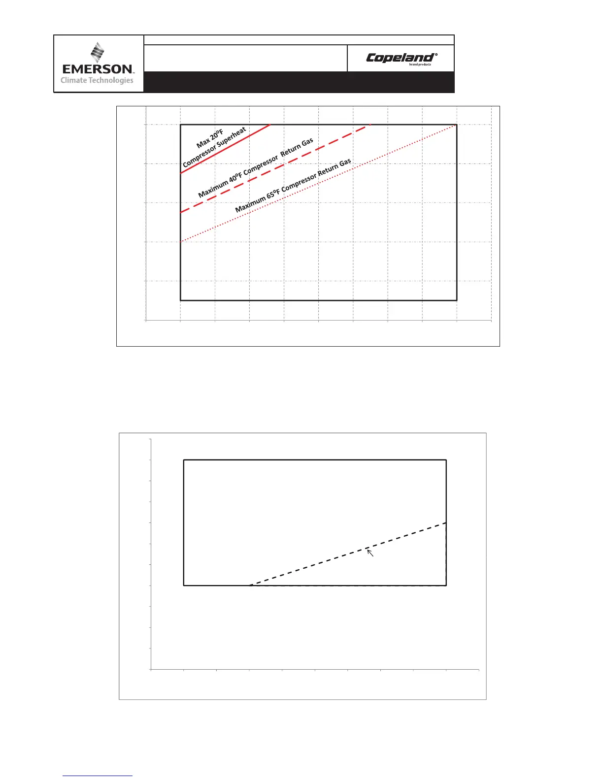
Figure 2 – Low Temperature Operating Envelope with Demand Cooling for
R-407A, R-407C and R-407F
* Copeland Discus Operating Map with head fan for R407A/C/F with average injection line depending on compressor
superheat/return gas. Points below the line Demand Cooling Injection would not be active. For example at -25°F evaporating
temperature 80°F condensing and 65°F return gas there would not be injection, but at the same evaporating temperature and
return gas temperature at 120°F condensing temperature the Demand Cooling would inject.
90
100
110
120
130
140
mperature (°F)
Demand Cooling
Required*
30
40
50
60
70
80
-
45 -40 -35
-
30 -25 -20 -15 -
10
-
50 5
Condensing T
Evaporang Temperature (°F)
Cooling Injecon Line
*If
Liquid
Injecon
Is
Not
Installed,
Recommend
265°F MAX
Discharge
Line
Temp.
Limit
Figure 3 – Low Temperature Operating Envelope for R-22 at 65°F Return Gas (with Head Fan)
30
50
70
90
110
130
-45 -40 -35 -30 -25 -20 -15 -10 -5 0 5
Condensing (F)
Evap (F)
*If Liquid Injecon Is Not Installed, Recommend 265°F MAX Discharge Line Temp. Limit
Injection lines represent maximum operation
point within discharge temperature limits of the
compressor.
Note: Injection lines shown are based on when
head fan is applied, however if Demand Cooling
is applied with R-407 series refrigerants a head
fan is NOT required.
 Loading...