Operating instruction
Thermo® Expansion Valves
TCLE, TJRE, TERE, TIRE, THRE
Emerson Climate Technologies GmbH www.emersonclimate.eu
Am Borsigturm 31 I 13507 Berlin I Germany Date: 29.06.2016 T_S_OI_ML_R06_862157.docx
General information and technical data:
• Refrigerants: see nameplate
• Evaporating Temperature Range:
a) for valves with pressure limitation (MOP): see
nameplate
b) for valves without pressure limitation:
+30° C to -45° C
• Max. Working Pressure PS: 31 bar
• Safe Working Temperature: 80° C
• Marking:
Safety instructions:
• Read installation instruction thoroughly. Failure
to comply can result in device failure, system
damage or personal injury.
• It is intended for use by persons having the
appropriate knowledge and skill. Before opening
any system make sure pressure in system is
brought to and remains at atmospheric pressure.
Do not leak any refrigerant into the atmosphere.
• Do not use on service conditions or fluids not
specifically cataloged, without prior approval of
Alco Controls.
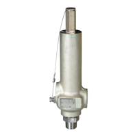
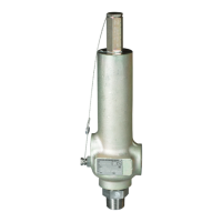
Installation: (Fig. 1)
1 Power Assembly 7 Body Flange
2 Remote Bulb Gasket
3 External Equalizer 8 Seat Gasket
Connection 9 Body Flange
4 Seal Cap 10 Cap Screws
5 Body Flange Gasket 11 Lugged Spring
6 Cage Assembly Carrier
1. Valves may be installed in any position, but should
be located as close as possible to distributor or
evaporator inlet.
2. Install line connections to valve so its flow arrow
corresponds to flow direction on flange. On valves
with solder connections remove cap screws, power
assembly, cage assembly and gaskets prior to
brazing.
3. Assemble valve after brazing, according to Fig 1,
making sure that lugs of spring carrier line up with
slots inside power assembly.
4. Tighten cap screws evenly to torque specification
35 Nm. Overtorqueing may result in valve body
damage.
5. Attach remote bulb to suction line as close to
evaporator outlet as possible in a horizontal run and
fix it, normally at the 4 or 8 o'clock position. Clean
surface of suction line before.
6. Connect one end of external equalizer line (OD = 6
mm = ¼ inch) to valve. Connect other end to
suction line slightly downstream from remote bulb
location and position it so that it cannot syphon oil
from the suction line.
7. Check for leaks, sufficient system refrigerant and
be sure no flash gas is present.
Superheat Adjustment: (Fig. 2)
ALCO Thermo
-Expansion Valves are factory preset
for optimum superheat settings. This setting should be
modified only if absolutely necessary. The
readjustment should be at the lowest expected
evaporating temperature:
1. Remove seal cap (1) on side of valve.
2. Turn adjusting stem clockwise to increase
superheat and counter-clockwise to decrease it.
Allen key X 99999 (2).
3. Reinstall seal cap. Wait 20 minutes before further
adjustments.
4. If refrigerant escapes use allen key X99999 (3) to
fix spindle gasket.
Pressure Evaporating temperature °C
Valve Refri- changes
+10 0 -10 -20 -30 -40
Series gerant per turn Static superheat changes
(bar) per turn of stem (K)
R 134a 0,05 0,4 0,5 0,6 0,9
R 22 0,05 0,3 0,3 0,4 0,5 0,7 1,0
TCLE R 404A 0,05 0,2 0,3 0,3 0,4 0,6 0,8
R 407C 0,05 0,2 0,3 0,4 0,6
R 507 0,05 0,2 0,3 0,3 0,4 0,5 0,7
TJRE R 134a 0,038 0,3 0,4 0,5 0,7
TERE, R 22 0,038 0,2 0,3 0,3 0,4 0,5 0,7
TIRE, R 404A 0,038 0,2 0,2 0,3 0,3 0,5 0,6
THRE R 407C 0,038 0,2 0,2 0,3 0,4
R 507 0,038 0,2 0,2 0,2 0,3 0,4 0,5
Note:
1. Foreign particles in Thermo
-Valve may cause
diaphragm failure, flooding or starving. Use of an
ALCO Filter Drier is strongly recommended.
2. Protect valve against excessive vibrations as it may
result in bulb tubing breaking.
Leakage test:
After completion of installation, a test pressure must
be carried out as follows:
- According to EN378 for systems which must
comply with European pressure equipment directive
97/23/EC
- To maximum working pressure of system for other
applications
Warning:
• Failure to do so could result in loss of
refrigerant and personal injury.
• The pressure test must be conducted by skilled
persons with due respect regarding the danger
related to pressure.