EasyManua.ls Logo

Emerson Anderson Greenwood 81 Series User Manual

Emerson Anderson Greenwood 81 Series
4 pages
To Next Page IconTo Next Page
Page #1 background imageLoading...
Page #1 background image
ANDERSON GREENWOOD SERIES 81 SPRING OPERATED PRESSURE RELIEF VALVES
INSTALLATION AND MAINTENANCE INSTRUCTIONS
© 2017 Emerson. All Rights Reserved.
Before installation these instructions must be fully read and understood
Emerson.com/FinalControl
Installation and Maintenance Instructions for
Series 81 Spring Operated Pressure Relief
Valves (SOPRV).
The intent of these instructions is to acquaint
the user with the storage, installation and
operation of this product. Please read these
instructions carefully before installation.
1 GENERAL
The Anderson Greenwood Series 81 Relief Valve
is a direct acting spring loaded valve for gas
service and uses a plastic seat and O-ring seals.
The intent of these instructions is to acquaint
the user with the maintenance of this product.
Please read these instructions carefully. This
product should only be used in accordance
with the applicable operating instructions and
within the application specifications of the
original purchase order. The Installation and
2 VALVE REPAIR (-4, -6, -8 ORIFICE)
Refer to Figure 1
2.1 Disassembly
2.1.1 Relieve spring tension and back
blowdown adjusting screw out two turns.
2.1.2 Remove inlet bushing, bushing seal and
valve internals.
2.1.3 Separate nozzle from guide by hitting top
of spindle on soft surface.
2.2 Repair
2.2.1 Hold spindle by skirt O.D. in soft jaw vise
and replace seat.
2.2.2 Examine nozzle and polish out any
scratches or nicks. Replace if necessary.
2.2.3 To obtain better seat seal with PTFE at
low set pressures, burnish seat against
nozzle by chucking spindle in lathe and
holding nozzle against spindle. Burnish
with small force and for short time as
PTFE readily deforms.
VCIOM-06062-EN 19/03
2.3 Assembly
Assemble in reverse order of disassembly.
Donot lubricate spindle or guide. Make sure
the nozzle is fully and evenly seated in guide.
This is a press fit joint. Lubricate threads and
pressure adjustment screw tip.
2.4 Soft goods repair kit
The part numbers for soft goods repair kits are
listed below. Each kit contains the seat and all
seals for the pressure ranges indicated.
Engineering Doc. #05.9040.071 Rev. N
TABLE OF CONTENTS
1. General ........................................................... 1
2. Valve repair (-4, -6, -8 orifice) ....................... 1
3. Valve repair (F, G, H and J orifice) ................ 2
4. Valve adjustment ........................................... 3
5. Seat leakage .................................................. 4
6. Set pressure change ..................................... 4
Operational Safety Instructions (available at
Emerson.com/FinalControl) should be fully read
and understood before returning this product to
service after maintenance.
Question and Answer IconNeed help?

Do you have a question about the Emerson Anderson Greenwood 81 Series and is the answer not in the manual?

Emerson Anderson Greenwood 81 Series Specifications

General IconGeneral
BrandEmerson
ModelAnderson Greenwood 81 Series
CategoryControl Unit
LanguageEnglish

Summary

1 GENERAL

Installation and Maintenance Instructions for Series 81 Spring Operated Pressure Relief Valves (SOPRV)

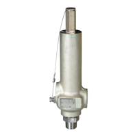
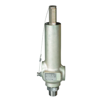
Provides an overview of the Series 81 Spring Operated Pressure Relief Valves (SOPRV).

Operational Safety Instructions

Read and understand safety instructions before returning product to service after maintenance.

2 VALVE REPAIR (-4, -6, -8 ORIFICE)

2.1 Disassembly

Steps for disassembling the valve, including relieving spring tension and removing internals.

2.2 Repair

Instructions for replacing the seat and examining/polishing the nozzle.

2.3 Assembly

Procedure for reassembling the valve in reverse order of disassembly.

2.4 Soft goods repair kit

Details part numbers for soft goods repair kits containing seats and seals.

3 VALVE REPAIR (F, G, H AND J ORIFICE)

3.1 Disassembly

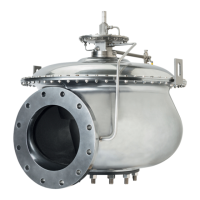
Steps for disassembling F, G, H, and J orifice valves, including vent hole notes.

3.2 Repair

Instructions for replacing the seat and examining/polishing the nozzle for specific orifices.

3.3 Assembly

Procedure for assembling F, G, H, and J orifice valves in reverse order of disassembly.

3.4 Soft goods repair kit

Set pressure range

Lists part numbers for soft goods repair kits for F, G, H, and J orifices.

SET PRESSURE RANGE

Valve operating characteristic Tolerance

Specifies tolerances for set pressure, cracking pressure, and reseat pressure.

4 VALVE ADJUSTMENT

4.1 General

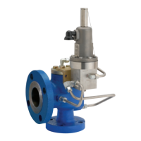
Explains that gas service valves have two adjustments for opening and closing pressure.

4.2 Set pressure

Instructions for adjusting the valve's set pressure using the spring adjustment screw.

4.3 Reseat pressure

Guidance on adjusting blowdown by turning the blowdown adjustment screw.

4.4 Adjustments tolerances

States that gas service valves have two adjustments for opening and closing pressure.

4.5 Adjusting equipment

Recommends equipment like accumulators for setting blowdown accurately.

BLOWDOWN ADJUSTMENT

Turns out of blowdown screw

Table indicating the turns of the blowdown screw for various orifices and pressure ranges.

5 SEAT LEAKAGE

5.1 General

Checks for leaks after repair, including seating, foreign particles, and correct seat material.

5.2 Seat sealing procedures

Procedure involving heating the valve to eliminate seat leakage.

6 SET PRESSURE CHANGE

Related product manuals