97
Installation
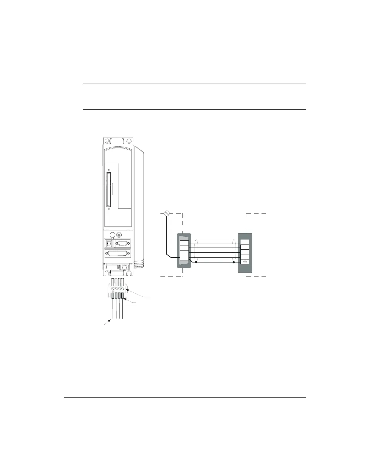
Note
The motor ground wire and shields must be run all the way back to the amplifier terminal
and must not be connected to any other conductor, shield or ground.
Figure 66: EN Motor Power Wiring Diagram
RST
Wire crimp ferrules are recommended:
If 14 to 16 AWG, use panduit #PV14-P47.
If 12 AWG, use Panduit #PV10-P55.
Tighten screws to 5 lb-in.
Important:
Ground should connect to drive and
motor only. Nothing should be connected
between these devices.
Front View
Connector Shell
R
S
T
Ground
Motor Power
Connection
Drive
PE
S
B
Shield
Green/Yellow
Black
T
C
Blue
2" or 3" Motors: PT06A-15-8SSR
4" Motors: MS3106A-20-15SSR
D
R
Brown
A
GND
Artisan Technology Group - Quality Instrumentation ... Guaranteed | (888) 88-SOURCE | www.artisantg.com
 Loading...