43
Setting Up Parameters
Pulse Mode Interpretation Group
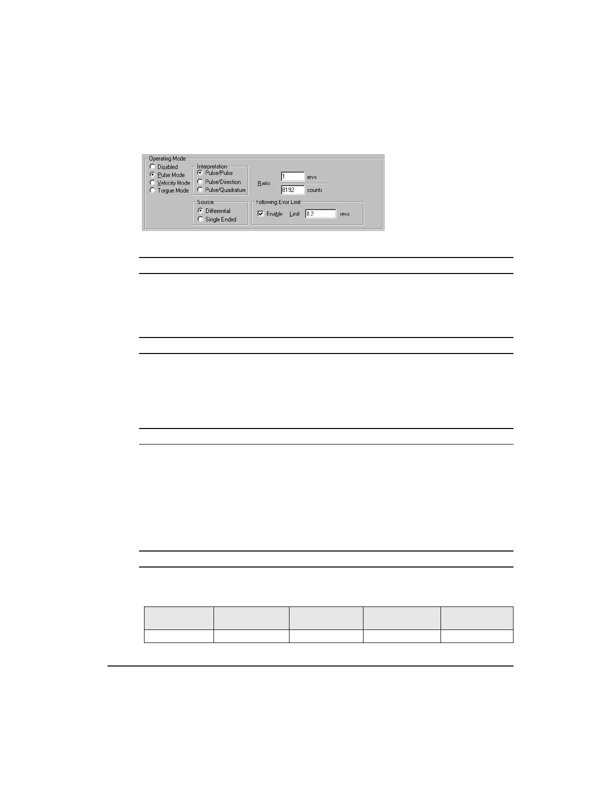
Figure 24: Operating Mode, Pulse Mode Selected
Pulse/Pulse Radio Button
Selecting this radio button puts your drive in Pulse/Pulse interpretation. In Pulse/Pulse mode,
pulses received on the A channel are interpreted as positive changes to the Pulse Position
Input, and pulses received on the B channel are interpreted as negative changes to the Pulse
Position Input.
Pulse/Direction Radio Button
Selecting this radio button puts your drive in Pulse/Direction interpretation. In Pulse
Direction mode, pulses are received on the A channel, and the direction is received on the B
channel. If the B is high, pulses received on the A are interpreted as positive changes to the
Pulse Position Input. If the B is low, pulses received on the A are interpreted as negative
changes to the Pulse Position Input.
Pulse/Quadrature Radio Button
Selecting this radio button puts your drive in Pulse/Quadrature interpretation. If Pulse
Quadrature is selected, a full quadrature encoder signal is used as the command. When B
leads A encoder counts received are interpreted positive changes to the Pulse Position Input.
When A leads B encoder counts received are interpreted as negative changes to the Pulse
Position Input. All edges of A and B are counted, therefore one revolution of a 2048 line
encoder will produce a 8192 count change on the Pulse Position Input.
Source Group
Differential Radio Button
Selects the differential hardware input of the drive to receive pulses (default) these pulse
inputs are as follows:
ECI-44 Terminal
Command
Connector Pin #
Pulse-Direction
Signal
Pulse-Pulse
Signal
Pulse Quadrature
Signal
Sync Enc In “A” 27 Pulse Pulse + A
Artisan Technology Group - Quality Instrumentation ... Guaranteed | (888) 88-SOURCE | www.artisantg.com
 Loading...