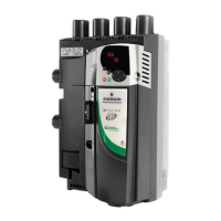
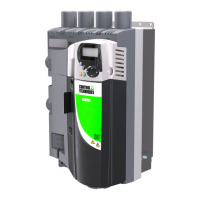
Do you have a question about the Emerson Copeland EVM Series and is the answer not in the manual?
It is strongly recommended to read through this entire manual for safe and correct installation.
Check for packaging or equipment damage that may have occurred during shipment. Ensure all components are included.
Provides information on how to install, start up, and set up the Copeland EVM drive.
Provides essential information about the drive, including model number, voltage, current, and serial number.
Details the function of each button on the drive's keypad for navigation and control.
Provides physical dimensions and weight specifications for different frame sizes of the EVM drive.
Provides guidelines for the physical installation and space requirements for mounting the EVM drive.
Details the wiring connections and termination resistor settings for installing option cards in the EVM drive.
Explains the proper grounding procedures for the EVM drive and its components for safety and EMC compliance.
Provides specific measurements for stripping power and motor cables for correct connection to the EVM drive.
Specifies the correct torque values for power, ground, and control wire connections on the EVM drive.
Guides the user on selecting the appropriate circuit breaker size based on NEC requirements and drive load.
Provides guidance on separating different types of wiring (mains, motor, control) in conduits for safety and UL compliance.
Details procedures for measuring insulation resistance of input power and motor cables, and motor windings.
Provides recommendations for achieving electromagnetic compatibility (EMC) in the drive system installation.
Details how to connect metallic parts and cabinet doors for effective high-frequency conduction and EMC.
Explains how to connect the ground connection (PE) to a central earth point for the drive system.
Guides on using screen earth kits for proper shielding and grounding of cables to minimize EMC issues.
Provides EMC guidelines for motor power cables, including categories and length limitations.
Classifies cable types based on their EMC performance characteristics for use with the EVM drive.
Explains how to adjust EMC protection class to C4 for corner-grounded networks and IT systems.
Describes how to check the motor's rotation direction after installation to ensure correct operation.
Illustrates the wiring connections for the EVM PRO version of the drive, including STO, Relay, and I/O terminals.
Presents a basic wiring diagram for the EVM drive, showing connections for keypad, relay, and I/O terminals.
Explains the terminal functions and wiring configurations for digital and analog inputs/outputs on the EVM drive.
Illustrates the menu structure and navigation paths for setting up the EVM drive.
Guides the user through the initial setup process by prompting for essential drive parameters.


