FR4 Mounting Instructions
Step 1:
Lift the drive out from the carton and remove the
packaging. The magnetic cores and cable ties are
only included in EMI version drive.
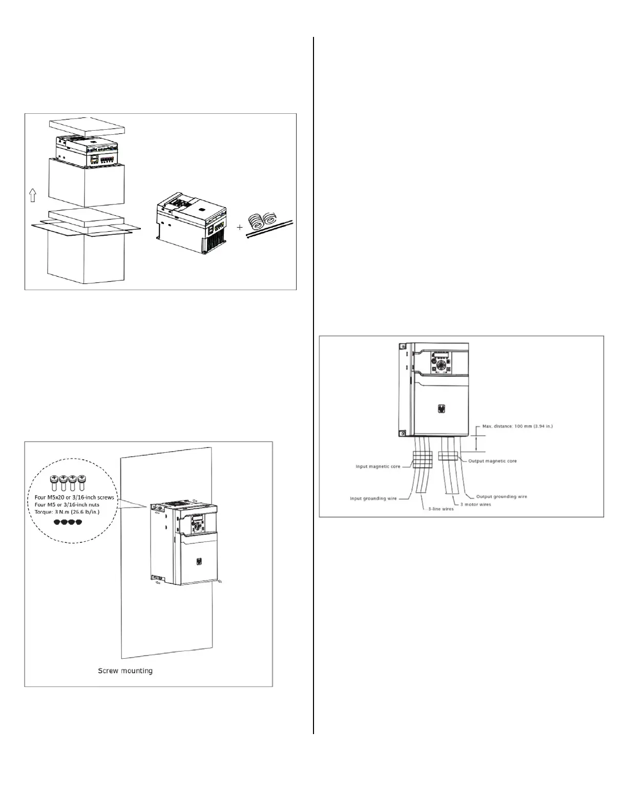
Step 3: (EMI version only)
Input wiring:
3P 230/480 V FR4 EMI version: Run the input wires (three
line wires + one grounding wire) through the input
magnetic core before connecting to the input terminal block
(L1/L2/L3) and grounding hole. Tie the input magnetic core
to the input wires with a cable tie.
3P 575 V FR4 EMI version: Run the input wires (three line
wires) through the input magnetic core before connecting
to input terminal block (L1/L2/L3). The input grounding wire
should not run through the input magnetic core. Tie the
input magnetic core to the input wires with a cable tie.
Output wiring:
3P 230/480/575 V FR4 EMI Version: Run three motor
wires through the output magnetic core before connecting
to output terminal block. The output grounding wire should
not run through the output magnetic core. Tie the output
magnetic core to the output wires with a cable tie.
The maximum distance between the input/output magnetic
core’s top surface is 100 mm (3.94 in.). All EVM non-EMI
version drives do not have input/ output magnetic cores.
Step 2:
Screw mounting: Attach the drive to the mounting
plate with four M5x20 (or 3/16 in.) screws and four M5
(or 3/16 in.) nuts. The opening dimension on the
mounting plate should follow required dimension
(refer to the dimension drawing in the instruction
leaflet).
 Loading...


