170
Epsilon Eb and EN Drives Reference Manual
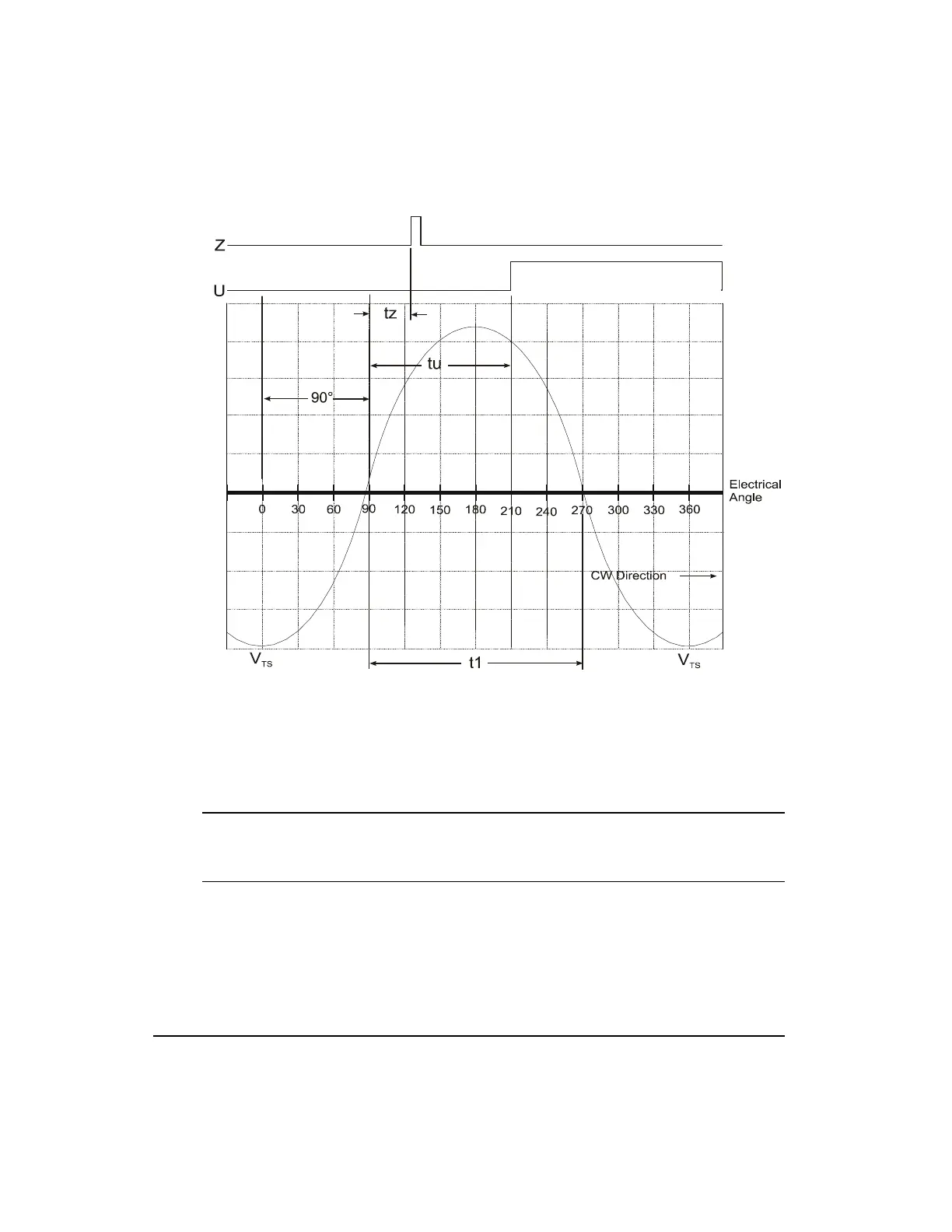
Figure 125: CW Electrical Angle Plot
In Figure 124 the electrical angle decreases from left to right and the positive peak of V
TS
occurs at zero degrees electrical. In Figure 125 the electrical angle increases from left to right
and the negative peak of V
TS
occurs at zero degrees electrical. Note that with a CW reference
rotation the negative peak of V
TS
is at zero electrical degrees and the electrical angle
decreases from left to right.
Note
If you cannot obtain a stable angle measurement between U or Z and V
TS
, check the
encoder to verify it has the proper cycles per revolution for your motors pole count.
Establishing a Standard Alignment
A typical encoder alignment practice is to set the rising edge of U to zero crossing of the rising
wave of V
SR
with the motor rotating CCW.
Artisan Technology Group - Quality Instrumentation ... Guaranteed | (888) 88-SOURCE | www.artisantg.com
 Loading...