44
Epsilon Eb and EN Drives Reference Manual
Differential Inputs are typically needed for pulse rate 7250 kHz or high ambient noise
environments.
Single Ended Radio Button
Selects the single ended hardware input of the drive to receive pulses (default) these pulse
inputs are as follows:
Ratio Formula
Defines the number of command pulses it will take to move the motor the distance specified
in the Pulse Mode Ratio Revolutions. The default value is 1 motor revolution per 8192 counts.
The coarsest ratio possible is 10 input counts per motor revolution. Setting a ratio to fewer
than 10 input counts per motor revolution will cause an Overspeed fault without generating
motion.
Following Error Limit Group
Enable Check Box
Check this box to enable or disable the Following Error Limit. The Following Error is the
algebraic difference between the Position Command and the Position Feedback. It is positive
when the Position Command is greater than the Position Feedback. If the absolute value of
the following error exceeds the value you enter here, the drive will generate a Following Error
fault. All accumulated Following Error will be cleared when the drive is disabled.
Following Error Limit
The Following Error Limit is functional in Pulse mode only. This limit is in motor revolutions
and has a range of .001 to 10.000 revolutions.
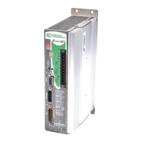
Sync Enc In “A/” 41 Pulse/ Pulse +/ A/
Sync Enc In “B” 26 Direction Pulse - B
Sync Enc In “B/” 40 Direction/ Pulse -/ B/
ECI-44 Terminal
Command
Connector Pin #
Pulse-Direction
Signal
Pulse-Pulse
Signal
Pulse Quadrature
Signal
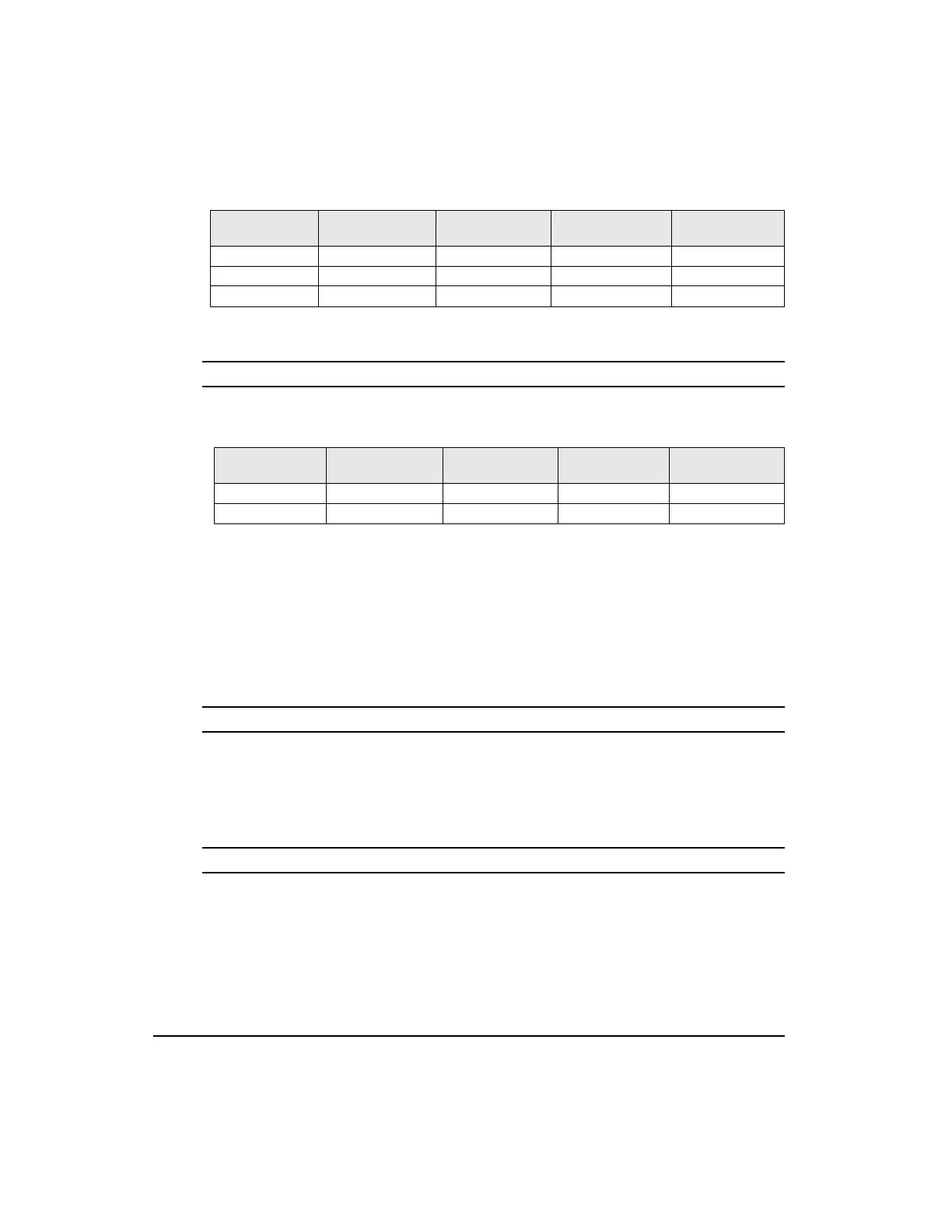
NC2 20 Pulse / Pulse + / A
NC1 36 Direction Pulse - / B
ECI-44 Terminal
Command
Connector Pin #
Pulse-Direction
Signal
Pulse-Pulse
Signal
Pulse Quadrature
Signal
Artisan Technology Group - Quality Instrumentation ... Guaranteed | (888) 88-SOURCE | www.artisantg.com