93
Installation
Auxiliary Logic Power Usage ( EN Only)
)
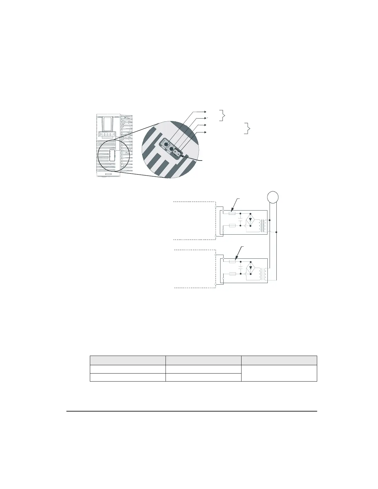
Figure 63: EN Auxiliary Power Supply Wiring Diagram
As shown in Figure 63, the auxiliary logic power connector is accessed through a plastic
punch-out tab located on top of the drive that reads "BUS/AUX". The auxiliary logic power
for each EN drive must be individually transformer isolated from the AC supply. The voltage
range is 127 to 373 VDC, at 21 Watts. This can be accomplished by isolating, rectifying and
filtering 90 to 264 VAC.
System Power Vo ltage
EN Drive Only 15 watts
127 to 373 VDC (Transformer isolated,
rectified and filtered 90 to 264 VAC)
EN Drive with FM Module 21 watts
Top View
-V
Bus
Use 16 to 18 AWG stranded wire
Bus
J2
J3
+ Auxiliary Supply
- Auxiliary Supply
J3 - Two position header.
The mating ALPC-006
cable is supplied
with the ALP Auxiliary
Power Supply.
+V Auxiliary
Supply
+V Auxiliary
Supply
-V Auxiliary
Supply
Drive #1
0.5 Amp
Fuses
0.5 Amp
Fuses
Drive #2
AC
-V Auxiliary
Supply
127 to 373
VDC
220µ
F
-
+
-
+
127 to 373
VDC
220µ
F
-
+
-
+
J3
J3
+
Artisan Technology Group - Quality Instrumentation ... Guaranteed | (888) 88-SOURCE | www.artisantg.com
 Loading...


