9
Operational Overview
Signal common connected to Drive Logic 0V (Sync Encoder Common 0V)
Pulse / : Commands motion on the falling edge (active edge).
Direction: Positive (+) motion when high (inactive) and Negative (-) motion when low
(active).
Pulse CW / : Commands positive (+) motion on the falling edge (active edge) of a pulse.
Pulse CCW /: Commands negative (-) motion on the falling edge (active edge) of a pulse.
A and B : Encoder Quadrature signal interpretation. When B leads A Positive (+)
motion commands will be generated, When A leads B, negative (-) motion
commands will be generated.
Note
Actual motor rotation direction will depend on pulse ratio polarity and setting of the
Positive Direction bit.
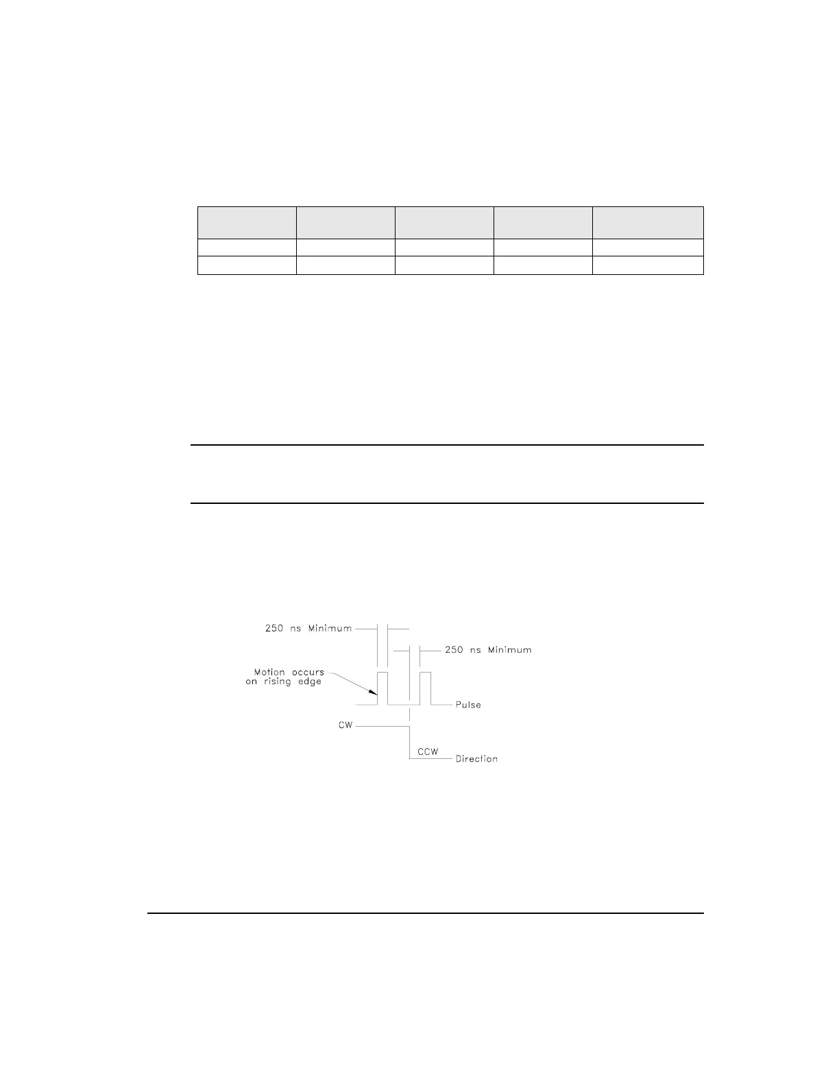
Pulse/Direction Interpretation
In Pulse/Direction interpretation, pulses are received on the A channel and the direction is
received on the B channel. If the B is high, pulses received on the A are interpreted as positive
changes to the Pulse Position Input. If the B is low, pulses received on the A are interpreted
as negative changes to the Pulse Position Input.
Figure 4: Pulse/Direction Signals, Differential Inputs
Pulse/Quadrature Interpretation
In Pulse/Quadrature interpretation, a full quadrature encoder signal is used as the command.
When B leads A encoder counts are received they are interpreted as positive changes to the
Pulse Position Input. When A leads B encoder counts are received they are interpreted as
ECI-44 terminal
Command
Connector Pin #
Pulse-Direction
Signal
Pulse-Pulse
Signal
Pulse Quadrature
Signal
NC2 20 Pulse / Pulse CW / A
NC1 36 Direction Pulse CCW / B
Artisan Technology Group - Quality Instrumentation ... Guaranteed | (888) 88-SOURCE | www.artisantg.com
 Loading...


