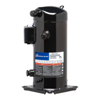
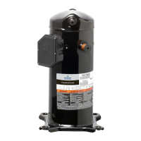
C6.2.7/0302-0903/E 5
The Copeland DTC valve is equipped with a custom bulb profile, which must be installed in the thermal well of the top
cap of the compressor, sensing the temperature closest to the discharge port. The DTC valve injects only when
cooling is needed and in the required amounts. The connection to the liquid line is a 3/8" braze
Valve Specifications
Set Point: 89.4°C ± 2.4°C (193°F ± 5°F)
Liquid Line Connection: 3/8"
Valve Installation
The valve bulb must be installed in the discharge cap thermal well to adequately control discharge temperatures. The
valve should be tightened on the injection fitting to a torque of 24-27 Nm (216-245 in. lbs.) It is also reccommended
that the valve is located perpendicular to the compressor orientation, in relation to the liquid inlet to the DTC valve,
however it will function properly in any orientation. The capillary tube connecting the valve to the bulb should be
positioned at least 13 mm away from the side of the scroll body to avoid contact during operation.
An insulating cap is supplied with the DTC Valve, which is applied over the DTC sensing bulb. The valve cap could be
replaced with thermal grease, if misplaced. This grease should be applied (minimum of 6 mm thick) to insulate and
protect the valve. It is recommended to spread a thin film of thermal grease around the DTC Valve bulb before
installing into the top cap well. We also recommend that a shut off valve in the liquid line is installed before the DTC
valve, for ease of service.(See Fig. 2: Compressor valve assembly procedure)
Compressor or Valve Service
Replacing a ZF compressor using the DTC Valve: We recommend replacing both the DTC Valve and the compressor
at the same time. If the the existing DTC valve is not replaced, then the removable valve filter should be cleaned
and/or replaced.

 Loading...
