C6.2.7/0302-0903/E 6
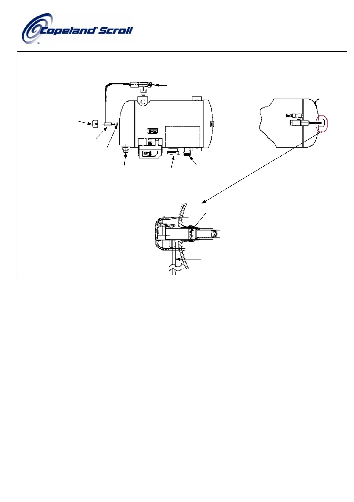
Figure 2: DTC valve assembly procedure
Legend to Fig.2:
1 Verify coil spring is seated in the ‘Groove’ located in the well on top of the compressor.
2 Thread the Discharge Temperature (DTC) valve onto the injection stub on the side of the compressor
3 Press the DTC bulb into the well on top of the compressor until the DTC bulb seats in the well.
4 Snap the Thermo. cap onto the DTC bulb on top of the compressor
5 The copper tube from the DTC bulb should be approximately 0.125mm (1/8”) from the compressor body.
Discharge
Stub
Oil Sight
Glass
Suction
Stub
4 Thermo Cap
1 Coil Spring
3 DTC Bulb
After
ssembl
Before
ssembl
Check
ssembl
Coil spring
5 Copper Tube
Liquid Inlet
Side
View
 Loading...