20 AGL_HP_VS_YHV2P_E_Rev0
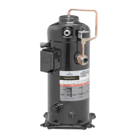
For the single-phase matched pairs of YHV*2P with ED3 drive, the following circuit diagrams
can be used:
Power circuit Control circuit
Legend
B1 ....... System controller F4 ........ LP switch
Q1 ....... Main switch K2 ........ Contactor (optional)*
D ......... Drive assembly RCD .... Residual current device type B or B+
F1, F6 . Fuses S1 ........ Auxiliary switch
F3 ....... HP limiter Grey = optional, depending on the system type
Figure 20: Wiring diagram for YHV*2P with single-phase drive
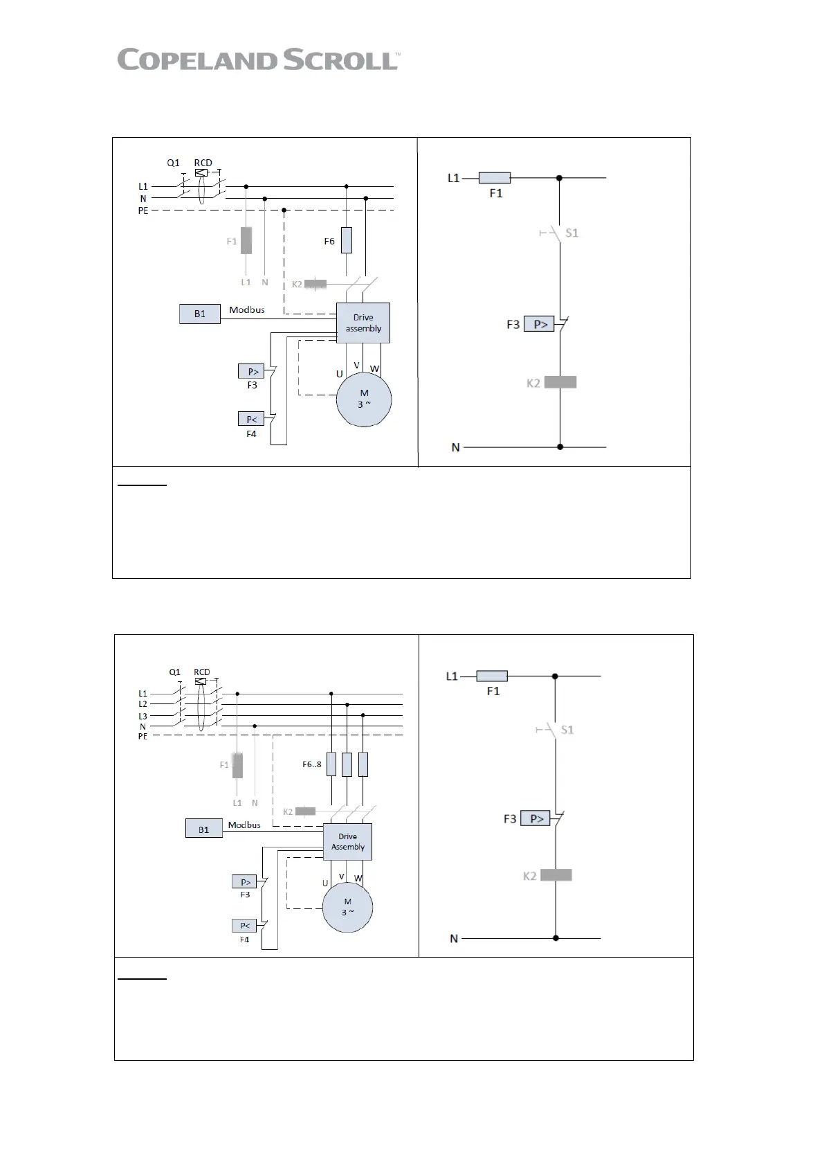
For the three-phase matched pairs of YHV*2P with ED3 drive, the following circuit diagrams
can be used:
Power circuit Control circuit
Legend
B1 ................. System controller F4 ........ LP switch
Q1 ................. Main switch K2 ........ Contactor (optional)*
D ................... Drive assembly RCD .... Residual current device type B or B+
F1, F6/7/8 ..... Fuses S1 ........ Auxiliary switch
F3 ....... ……...HP limiter Grey = optional, depending on the system type
Figure 21: Wiring diagram for YHV*2P with three-phase drive
* Additional contactor (K2) needed only on drives without STO (Safe torque off) safety input!
 Loading...