7
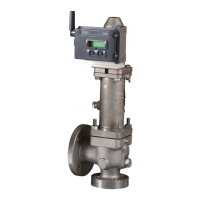
CROSBY STYLE JOS-E, JBS-E, JLT*-JBS-E, JLT*-JOS-E VALVES
InstallatIon and MaIntenance InstructIons
5.6 Valve operation
Crosby Style JOS-E/JBS-E valves intended for
compressible fluid service and tested with air
or steam will open with a sharp clear popping
action at the set point. Valves for liquid service
tested with water are considered open when
there is a continuous unbroken stream of liquid
flowing from the valve.
5.7 Set pressure changes
Set pressure changes beyond the specified
spring range will necessitate a change in the
valve spring assembly consisting of the spring
and two fitted spring washers. The new spring
and washers must be obtained from Emerson
and the valve must be reset and the nameplate
restamped by an authorized valve repair facility.
TABLE 1
Service Orifice size Nozzle ring setting (below highest lock position)
Style JOS-E/JBS-E pressure relief valve recommended nozzle ring settings
Vapor and gases
D through J -5
K through N -10
P through T -15
Style JLT-E pressure relief valve recommended nozzle ring settings
Liquids and gases
D, E, and F -2
G, H, and J -3
K and L -5
M and N -10
P and Q (see Table 2)
R and T (see Table 2)
5.8 Set pressure adjustment
Before making any adjustments, reduce the
pressure under the valve seat to at least 10%
below the stamped opening pressure. This will
prevent seat damage due to turning of the disc
on the nozzle seat and minimize the chance of
an inadvertent valve opening. A strong (high)
ring position is necessary to obtain a good clean
popping action of the valve on air or gas with
the limited volume available on the test bench.
5.8.1
(Not required for testing on liquid). Remove
the nozzle ring set screw and raise the
nozzle ring until it touches the disc holder,
then back it down two (2) notches. Exercise
care in counting the number of notches
moved so that the ring can be returned to
its proper position following testing.
Moving the notches on the nozzle ring to
the left will lower the nozzle ring.
Replace the nozzle ring set screw before
each set pressure test. The set screw
must engage one of the ring notches,
being careful that it does not bear on the
top of a tooth.
5.8.2 Remove the cap or lifting lever following
the instruction for valve disassembly
(seeparagraph 6).
5.8.3 Loosen the adjusting bolt nut and turn the
adjusting bolt clockwise to increase set
pressure or counterclockwise to reduce
set pressure.
5.8.4 Retighten the adjusting bolt nut following
each adjustment.
5.8.5 Two or three consecutive valve openings
at the same pressure are necessary to
verify the opening pressure accurately.
5.8.6 Opening pressure tolerance shall comply
with ASME Section VIII Division 1 UG-136
(d) (1) as below or other tolerance may
be used so long as they meet ASME
requirement:
The set pressure tolerance for pressure
relief valves shall not exceed ±2 psi
(15 kPa) for pressures up to and including
70 psi (500 kPa) and ±3% for pressures
above 70 psi (500 kPa)
5.8.7 Once the set pressure has been
established, lower the nozzle ring to
the installed ring position as indicated
in Table 1 and replace the nozzle ring
set screw as described above. Seal wire
the adjusting bolt and adjusting ring set
screw with identifying seals.
5.9 Nozzle ring settings
The nozzle ring adjustment is made at the
factory and resetting in service is seldom
necessary. Should it be necessary to change
blowdown or reduce valve simmer, the nozzle
ring may be adjusted as follows: (see the next
paragraph for P, Q, R and T orifice Style JLT).
CAUTION
Should any adjustments be made while the valve is
installed on a pressurized system, the valve should
be gagged while ring adjustments are made.
NOTE
Minus sign indicates number of ring notches below starting position of nozzle ring which is the highest position
with the valve closed (contact with disc holder).
 Loading...
