Page 10
Product Information / Produktinformation
A6151
Shaft Vibration Monitor
1.5 Installation and Mounting
A prepared 3U slot in a 19” rack, or other Intermas−compatible enclosure, is required for
mounting the A6151 monitor. The slot must be fitted with a 48−pin plug connector (DIN 41612,
design F 48 M). The pin assignment is listed in the following table.
d
b z
2
UN+ (+ 24V) U− (0V/Common) UB+ (+24V, redundant)
2
4
A (RS 485) GND (BP, Common, RS 485) B (RS 485)
4
6
Supply2+ (sensor) Supply1− (sensor) Supply1+ (sensor)
6
8
AIN2− (Input) Supply2− (sensor) AIN1− (Input)
8
10
AIN2+ (Input) GND AIN1+ (Input)
10
12
NGL2 (scaled dc−output) GND NGL1 (scaled dc−output)
12
14
EO1 (voltage output1) EI1 (voltage input1) AC1 (sensor raw signal1)
14
16
EO2 (voltage output2) EI2 (voltage input2) AC2 (sensor raw signal2)
16
18
GWM (limit value) I1− (current output common) I1+ (current output CH1)
18
20
NC I2− (current output common) I2+ (current output CH2)
20
22
KEY−N (key signal input) GND ES (external lock)
22
24
SC−A (oper. principle alert) GND SC−D (oper. principle danger)
24
26
D1−C (danger1 collector) A1−C (alert1 collector) CC1−C (ch. clear1 collector)
26
28
D1−E (danger1 emitter) A1−E (alert1 emitter) CC1−E (ch. clear1 emitter)
28
30
D2−C (danger2 collector) A2−C (alert2 collector) CC2−C (ch. clear2 collector)
30
32
D2−E (danger2 emitter) A2−E (alert2 emitter) CC2−E (ch. clear2 emitter)
32
1.5.1 Jumper RS 485
RS 485 bus operation requires an electrical terminator on the first and last bus device.
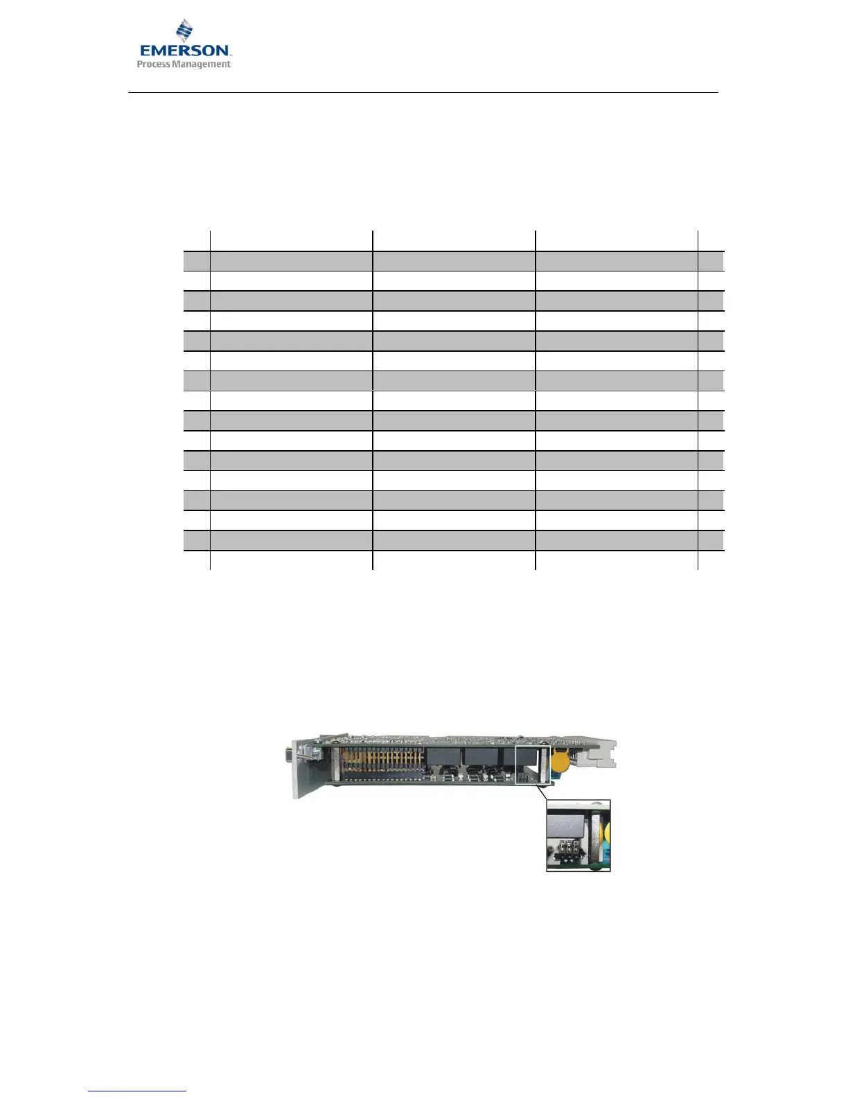
This is done with plug−in jumpers, that are on the controller board. The figure shows the position
of the jumpers.
To activate the bus terminator and to place lines “A” and “B” on the references, plug the jumpers
as shown in Fig. b). Fig. a) shows the jumper position for deactivated bus termination and open
references (delivery status).
• Plug−in jumper 1−2 closed: Bus line “B” via pull−down resistor on ground
• Plug−in jumper 3−4 closed: 120 Ω resistor between “A” and “B”
• Plug−in jumper 5−6 closed: Bus line “A” via pull−up resistor on +5 V



 To Next Page