Page 12
Product Information / Produktinformation
A6151
Shaft Vibration Monitor
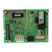
3. Use a cross head screwdriver to remove the four cross−headed screws, identified with the
arrows, in the following figure.
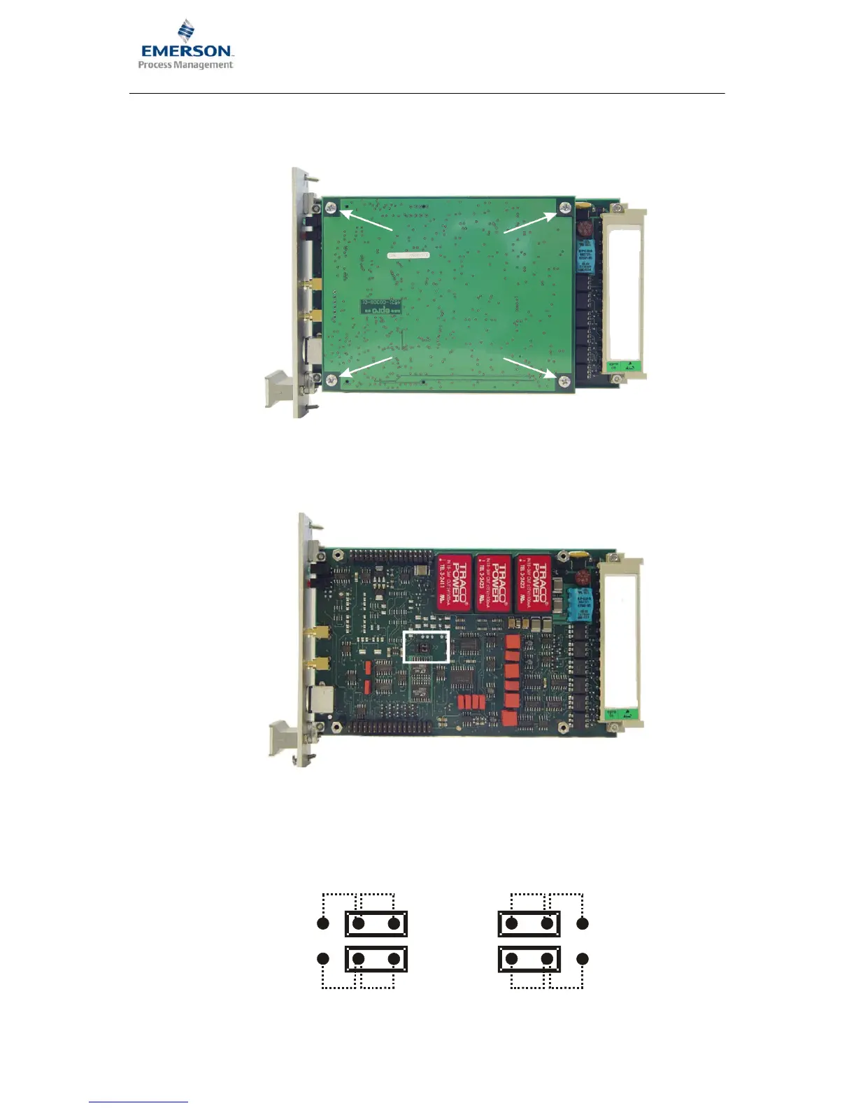
4. Carefully pull the controller board off the main board without tilting it. The position of the J2
jumpers on the main bard is identified with a white frame in the following figure.
5. To switch the raw sensor signal to terminals z14 and z16 place the jumpers as shown in b).
If the jumpers are set as shown in a) then the dynamic portion of the sensor signal is applied
on terminals z14 and z16.
J2
z14:
z16:
AC1
AC2
SENS1
SENS2
J2
z14:
z16:
AC1
AC2
SENS1
SENS2
a)
b)
 Loading...