1592033080 XR60CHC EN r1.0 2019.01.30 XR60CHC 2/6
8 DEFROST
8.1 DEFROST MODE
Any defrost operation can be controlled in the following way:
• EdF=rtC: by using an internal real-time clock (only for models equipped with RTC)
• EdF=in: timed defrost, in this case a new defrost will start as soon as the idF timer elapses
8.2 TIMED OR PROBE CONTROLLED MODE
Two defrost modes are available: timed or controlled by the evaporator’s probe. A couple of
parameters is used to control the interval between defrost cycles (idF) and its maximum length (MdF).
During the defrost cycle is possible to select some different display indications by using the dFd
parameter. These modes are available with any kind of defrost type:
• tdF=EL: electric heater defrost
• tdF=in: hot gas defrost
9 DIGITAL OUTPUT CONFIGURATION
Depending on the model, one or more digital outputs (relays) can be configurated with one of the following
functionalities.
9.1 ON/OFF OUTPUT (OAX = ONF)
When oAx=onF, the output is activated when the controller is turned on and de-activated when the
controller is turned off.
9.2 DEAD BAND REGULATION
With oAx=db the output can be used to control, for example, a heater element. It is used to implement
a dead band regulation. If so:
• oAx=db cut in is SET-HY
• oA1=db cut out is SET
9.3 ALARM OUTPUT
With oAx=ALr the output operates as alarm output. It is activated every time an alarm happens. Its
status depends on the tbA parameter: if tbA=Y, the output is deactivated by pressing any key.
If tbA=n, the alarm output stays on until the alarm condition recovers.
9.4 ACTIVATION DURING ENERGY SAVING CYCLES
With oAx=HES, the output is activated when the energy saving cycle begins.
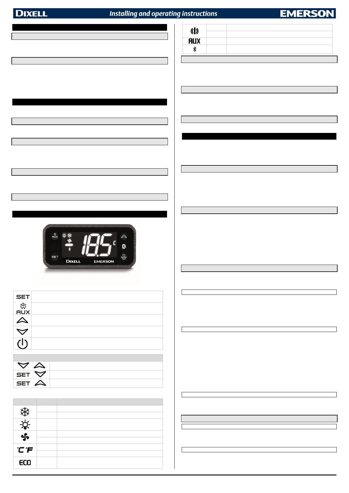
10 FRONT PANEL COMMANDS
10.1 SET POINT MENU
The SET key gives access to a quick menu where it is possible to see:
• the set point value
• the real set point value (rSE)
Push and release the SET key five times or wait for 60 sec to return to normal visualization.
10.2 CHANGE THE SETPOINT
1. Push the SET key for more than 3 sec to change the Set point value;
2. The value of the set point will be displayed and the “°C” LED starts blinking;
3. To change the Set value, push the UP or DOWN button.
4. To memorise the new set point value, push the SET button again or wait for 60 sec.
10.3 START A MANUAL DEFROST
Push the DEFROST
button for more than 3 sec to start a manual defrost.
11 PARAMETER MENU
The device has a parameter menu available from keyboard and where it is possible to modify some specific
parameters. A couple of parameter levels are present:
- PR1: user menu, standard parameters are placed into this menu
- PR2: protected menu, application specific parameters are placed here. A password can be
used to protect these values from unauthorized modification.
11.1 MENU NAVIGATION
A tree-structured menu is implemented to simplify the parameter browsing and modification. Follow the button
functions (valid both in PR1 and PR2):
- SET: used to enter a submenu or a stored value
- UP and DOWN: used to scroll the menu labels, the parameters into a submenu and to modify a
parameter value
- AUX/DEF: used to go back to the upper menu level (for example, from a submenu list of
parameters to the main menu labels)
11.2 CHANGE A PARAMETER VALUE
To change a parameter value, operate as follows:
1. Enter the Programming mode by pressing the SET+DOWN buttons for 3 sec (“°C” LED starts
blinking).
2. Select the required parameter. Press the SET button to display its value
3. Use UP or DOWN buttons to change its value.
4. Press SET to store the new value and move to the following parameter.
To exit: Press SET+UP buttons or waits for 15 sec without pressing any button.
NOTE: The modified value will be stored even if the programming mode ends by timeout.
11.3 PROTECTED LEVEL
The Protected Level has all the parameters of the instrument. This level is password protected. The
default password is: “000”. It is strongly recommended to change the standard password after ending
the installing operations.
11.3.1 ENTER THE PROTECTED LEVEL
1. Enter the Programming mode by pressing SET+DOWN buttons for 3 sec (°C or °F
LED starts
blinking)
2. Released the buttons and then search for submenu Pr2
3. Per SET button and then insert the password value
4. Confirm with SET. If the password is correct, the label “Pr2” will blink for some time and then
protected parameter menu will be enabled.
11.3.2 PROTECTED MENU
1. Select the parameter to modify
5. Press the SET key to display its current value
6. Use UP or DOWN to change its value
7. Press SET to store the new value and move to the following parameter
To exit: Press SET+UP or wait for 15 sec without pressing any button.
NOTE:
1. If there are no parameters into the User Level, after 3 sec the “nP” label will be displayed. Go to
submenu Pr2 and follow the previous procedure.
2. The modified value will be stored even if the programming mode ends by timeout.
3. Modify the par. PSU (when into Protected Level) to change the current password
11.3.3 MOVE PARAMETERS THROUGH LEVELS
Each parameter present into the Protected Level can be moved into the User Level by pressing both
SET+DOWN buttons. If a parameter is into the User Level, when visualized into the Protected Level it
will have also the decimal point.
11.4 KEYBOARD MANAGEMENT
11.4.1 TEMPORARY LOCK
1. Keep both UP and DOWN buttons pressed for more than 3 sec.
2. The “oFF” label will be displayed and the keyboard will be locked. If any button is pressed more
than 3 sec, the “oFF” message will be displayed.
11.4.2 TEMPORARY UNLOCK
Keep both UP and DOWN buttons pressed together for more than 3 sec till the “on” message will be
displayed.
 Loading...