1592033080 XR60CHC EN r1.0 2019.01.30 XR60CHC 5/6
START DEFROST (ixF=dEF)
It starts a defrost if there are the right conditions. After finishing any defrost, the normal regulation will
restart only if the digital input is disabled, otherwise the instrument will wait until the MdF safety time is
expired.
ENERGY SAVING (ixF=ES)
The energy saving mode will be enabled / disabled with the digital input.
MOTION SENSOR (ixF=EMt)
It counts the motion sensor detections.
AUXILIARY OUTPUT (ixF=AUS)
The AUX output (if present and configured) will be enabled / disabled with the digital input.
EXTERNAL WARNING ALARM (ixF=EAL)
It is used to detect an external alarm. It does not lock the regulation.
EXTERNAL LOCK ALARM (ixF=bAL)
It is used to detect any critical external alarm. It locks immediately the regulation.
EXTERNAL PRESSURE ALARM (ixF=PAL)
It is used to detect any pressure external alarm. This signal locks the regulation after nPS events in
dxd interval od time.
EVAPORATOR FAN MODE (ixF=FAn)
It is used to control the evaporator fan.
REMOTE HOLYDAY MODE (ixF=HdF)
It is used to force the holyday mode.
REMOTE ONOFF (ixF=onF)
It is used to switch ON and OFF the device remotely.
LIGHT OUTPUT (ixF=LiG)
It is used to control the light output.
CHANGE CONFIGURATION (ixF=CC)
It is used to change the controller configuration.
MOTION SENSOR DETECTOR (ixF=EMt)
To use the X-MOD motion sensor. Please note that motion sensor can be connected only to the
HOTKEY port, so it needs digital input 2 properly configurated.
14 INSTALLATION AND MOUNTING
Instrument XR60CHC shall be mounted on vertical panel, in a
29x71 mm hole, and fixed using the special bracket supplied.
The temperature range allowed for correct operation is 0 to 60°C.
Avoid places subject to strong vibrations, corrosive gases,
excessive dirt or humidity. The same recommendations apply to
probes. Let air circulate by the cooling holes.
The MDP/CX rear cover can be used to increase the protection
from water and dust.
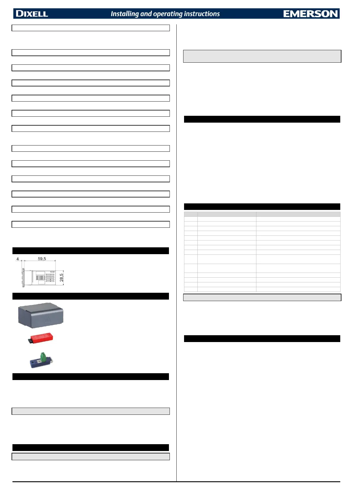
The HOT-KEY is used for a quick and easy upload (from device
to HOT-KEY) or download (from HOT-KEY to device) the
parameter map.
The XJ485LE serial interface converts the TTL output into an
RS485 signal that can be used to connect the unit to the
controlling and supervising system. Please note that other
version of this converter does not work with XR-CHC devices.
16 ELECTRICAL CONNECTIONS
The instrument is provided with screw terminal block to connect cables with a cross section up to
2.5mm
2
. Before connecting cables make sure the power supply complies with the instrument’s
requirements. Separate the probe cables from the power supply cables, from the outputs and the
power connections. Do not exceed the maximum current allowed on each relay, in case of heavier
loads use a suitable external relay.
16.1 PROBES
The probes shall be mounted with the bulb upwards to prevent damages due to casual liquid
infiltration. It is recommended to place the thermostat probe away from air streams to correctly
measure the average room temperature. Place the defrost termination probe among the evaporator
fins in the coldest place, where most ice is formed, far from heaters or from the warmest place during
defrost, to prevent premature defrost termination.
17 USE THE HOT-KEY
17.1 SAVE PARAMETERS IN A HOT-KEY (UPLOAD FROM INSTRUMENT)
1. Program one controller with the front keypad.
2. When the controller is ON, insert the “HOT-KEY” and push UP button; the “UP” message
appears followed a by flashing “End”
3. Push “SET” key and the “End” will stop flashing.
4. Turn OFF the instrument and then remove the “HOT-KEY”. At the end turn the instrument ON
again.
NOTE: the “Err” message appears in case of a failed programming operation. In this case push again
the UP button if you want to restart the upload again or remove the “HOT-KEY” to abort the operation.
17.2 COPY PARAMETERS FROM A HOT-KEY (DOWNLOAD PARAMETER
VALUES)
1. Turn OFF the instrument.
2. Insert a programmed “HOT-KEY” into the 5-PIN port and then turn the Controller ON.
3. The parameter list of the “HOT-KEY” is automatically copied into the controller memory. During
this operation the “do” message will blink
4. A flashing “End” label will inform that the operation was successful
5. Remove the “HOT-KEY”.
6. After some seconds the instrument will restart, using with the new parameters.
NOTE: the message “Err” is displayed for failed programming. In this case turn the unit off and then on
if you want to restart the download again or remove the “HOT-KEY” to abort the operation.
18 INTERNAL MEMORY
The controller has an internal memory where are stored:
- Two different parameter maps identified as C1 and C2
- Factory default configurations for both C1 and C2 parameters map
The controller is always shipped with:
- Parameter map C1 = factory default configuration C1
- Parameter map C2= factory default configuration C2
Any modification to parameter map C1 or C2 does not change the default factory values.
It is possible to change parameter map between C1 and C2 by using a digital input or a button properly
configurated (ixF or LG2=CC).
It is possible to restore factory defaults values for both C1 or C2 parameters map by using UP2=LdC (Load
default configuration) function.
NOTES:
- If controller is using C1 parameter map, the factory default configuration C1 will be reloaded
overwriting C1 parameter map. The same for parameter map C2.
- The factory default configurations are read only (it is not possible to modify them on the field).
19 ALARM SIGNALLING
Compressor output according to Con e CoF
Linked temperature alarm is not managed
Maximum temperature alarm
Minimum temperature alarm
Maximum temperature for second
temperature alarm
Minimum temperature for second
temperature alarm
Door open more than dxd time
Compressor and fans restarts
19.1 ALARM RECOVERY
Probe alarms “P1”, “P2”, “P3” and “P4” start some seconds after the fault in the related probe; they
automatically stop some seconds after the probe restarts normal operation. Check connections before
replacing the probe. Temperature alarms “HA”, “LA”, “H2” and “L2” automatically stop as soon as the
temperature returns to normal values. It is possible to reset the “EE” alarm by pressing any button.
The alarms “EA”, “CA” and “dA” will automatically stop as soon as the digital input is disabled.
The internal buzzer can be muted by pressing any key if parameter tbA=Y.
20 TECHNICAL DATA
Housing: self-extinguishing ABS
Case: frontal 32x74 mm; depth 60mm
Mounting: panel mounting in a 71x29mm panel cut-out
Body Protection: IP20
Frontal protection: IP65
Terminal blocks: Screw terminal block 2.5 mm
2
wiring
Power supply: (according to the model) 230Vac 10%, 50/60Hz; 110Vac 10%, 50/60Hz
Power absorption: 3.5VA max
Display: 3-digit LED, H=14.2 mm
Inputs: up to 4 NTC, PTC or PT1000 probes
Digital input: up to 2 voltage free contacts
Relay outputs: Compressor SPST 16(5)A, 250VAC or SPST 20(8)A, 250VAC
oA2: SPDT 8(2)A, 250VAC;
oA3: SPST 8(3)A, 250VAC or SPST 5(2)A, 250VAC
Data storing: EEPROM
Kind of action: 1B
Pollution degree: 2
Software class: A
Rated impulsive voltage: 2500V; Overvoltage Category: II
Operating temperature: 0 to 60°C (32 to 140°F)
Storage temperature: -25 to 60°C (-13 to 140°F)
Relative humidity: 20 to 85% (no condensing)
Measuring and regulation range:
NTC -40 to 110°C (-40 to 230°F)
PTC -55 to 150°C (-67 to 302°F)
PT1000 -100 to 200°C (-148 to 392°F)
Resolution: 0.1°C or 1°C (selectable)
Accuracy (ambient temp. 25°C):

 Loading...