1592034020 XR77CHC EN r1.0 2019.01.31 XR77CHC 2/7
8 CONDENSER FAN
8.1 GENERAL DESCRIPTION
The condenser fan is can be managed by dedicated control. To enable it, a condenser probe must be
selected by using par. FAC. Here follows the description of all the related parameters:
• FAC: to select the condenser fan probe
• St2: to select the condenser fan deactivation setpoint
• HY2: differential for condenser fan activation
• FCC parameter it can be selected the condenser fan working mode:
o FCC=C-n: condenser fan will switch ON and OFF with the compressor and will
not run during defrost
o FCC =o-n: condenser fan will run even if the compressor is off, and will not run
during defrost
o FCC =C-Y: condenser fan will switch ON and OFF with the compressor and will
run during defrost
o FCC =o-Y: condenser fan will run continuously, also during defrost.
9 DEFROST
Two defrost modes are available through the tdF parameter: defrost through electrical heater
(tdF=EL) and hot gas defrost (tdF=in).
The defrost interval depends on the presence of the RTC (optional). The internal RTC is controlled by means
of the EdF parameter:
• EdF=in: the defrost is made every idF time – standard way for controller without RTC.
• EdF=rtC: the defrost is real time controlled, depending on the day enabled in the parameters
dd1…dd7 and the hours set in the parameters Ld1...Ld6.
Other parameters are used to control defrosting cycles: the maximum length (MdF) and defrosting modes:
timed or controlled by the evaporator’s probe (P2P).
• At the end of defrost dripping time is started, its length is set in the Fdt parameter. With Fdt=0 the
dripping time is disabled.
9.1 SYNCHRONIZED DEFROST
This defrost function requires:
- To set a digital input of any controller as ixF=dEF
- To connect (by wire) all digital inputs set as ixF=dEF
A maximum number of 20 controllers can be used in this configuration.
The Synchronized defrost mode is enabled by par. SYd=SYn. After any defrost request (received by RTC,
timed by par. idF, manually by defrost button or by digital input set as dEF), all controllers will activate their
own defrost phase. When a controller ends its proper defrost phase, it releases the defrost line and load its
dripping time. At the end of the dripping time the normal regulation will restart. The other controllers follow the
same logic.
9.2 RANDOM DEFROST
A random defrost mode can be enabled by par. Syd=rnd. After any defrost request (received by RTC or timed
by par. idF) a random delay will be added. At the end of the added delay the defrost will start. The random
function lead to desynchronize the start of the defrost phases in those cases where more than a cabinet is
installed in the same “island”. The maximum defrost delay is linked to the following parameters:
- Mdf=maximum time for any defrost
- ndE=delay multiplier
by the following formula:
MAX_DEFROST_DELAY = Mdf*ndE (min)
For example: if ndE=10 and Mdf=20 min, the total interval to complete the defrost phase will be 200 min
(worst case).
NOTE:
- take care about the interval of time available for defrost. It must be used for selecting both MdF and
ndE values
the higher is the ndE value and the better is the result in terms of desynchronization. On the other side, the
longer will be the total interval of time required to complete defrosts
10 DIGITAL OUTPUT CONFIGURATION
Depending on the model, one or more digital outputs (relays) can be configurated with one of the following
functionalities.
10.1 CONFIGURABLE OUTPUT
10.1.1 LIGHT OUTPUT
With oAx=LiG the relay operates as light output.
10.1.2 DIGITAL OUTPUT ACTIVATION
The auxiliary output can be managed by digital inputs (oAx=AUS, i1F or i2F=AUS): with oAx=AUS
and i1F, i2F=AUS the output is switched on and off following the linked digital input status.
10.1.3 AUXILIARY THERMOSTAT
The auxiliary regulator can be used to manage the auxiliary output. Here follow the involved
parameters:
• ACH: kind of regulation for the auxiliary relay: Ht = heating; CL = cooling
• SAA: set point for auxiliary relay
• SHY: differential for auxiliary relay
• ArP: probe for auxiliary relay
• Sdd: auxiliary output off during defrost
10.1.4 TIMED ACTIVATION
The following parameters can be used to define fixed activation and deactivation intervals.
• btA: base time for auxiliary output activation and deactivation intervals
• Ato: auxiliary activation interval
• AtF: auxiliary deactivation interval
10.1.5 GENERAL NOTES
if oAx=AUS and ArP=nP (no probe for auxiliary digital output) the AUX output can be managed:
• by digital input if i1F=AUS or i2F=AUS
• by auxiliary button (if set as AUS)
• by serial command (Modbus protocol)
• by fixed interval of time if Ato>0 and AtF>0 (if Ato=0 or AtF=0 the auxiliary output is disabled)
10.2 ON/OFF OUTPUT (OAX = ONF)
When oAx=onF, the output is activated when the controller is turned on and de-activated when the
controller is turned off.
10.3 DEAD BAND REGULATION
With oAx=db the output can be used to control, for example, a heater element. It is used to implement
a dead band regulation. If so:
• oAx=db cut in is SET-HY
• oA1=db cut out is SET
10.4 ALARM OUTPUT
With oAx=ALr the output operates as alarm output. It is activated every time an alarm happens. Its
status depends on the tbA parameter: if tbA=Y, the output is deactivated by pressing any key.
If tbA=n, the alarm output stays on until the alarm condition recovers.
10.5 ACTIVATION DURING ENERGY SAVING CYCLES
With oAx=HES, the output is activated when the energy saving cycle begins.
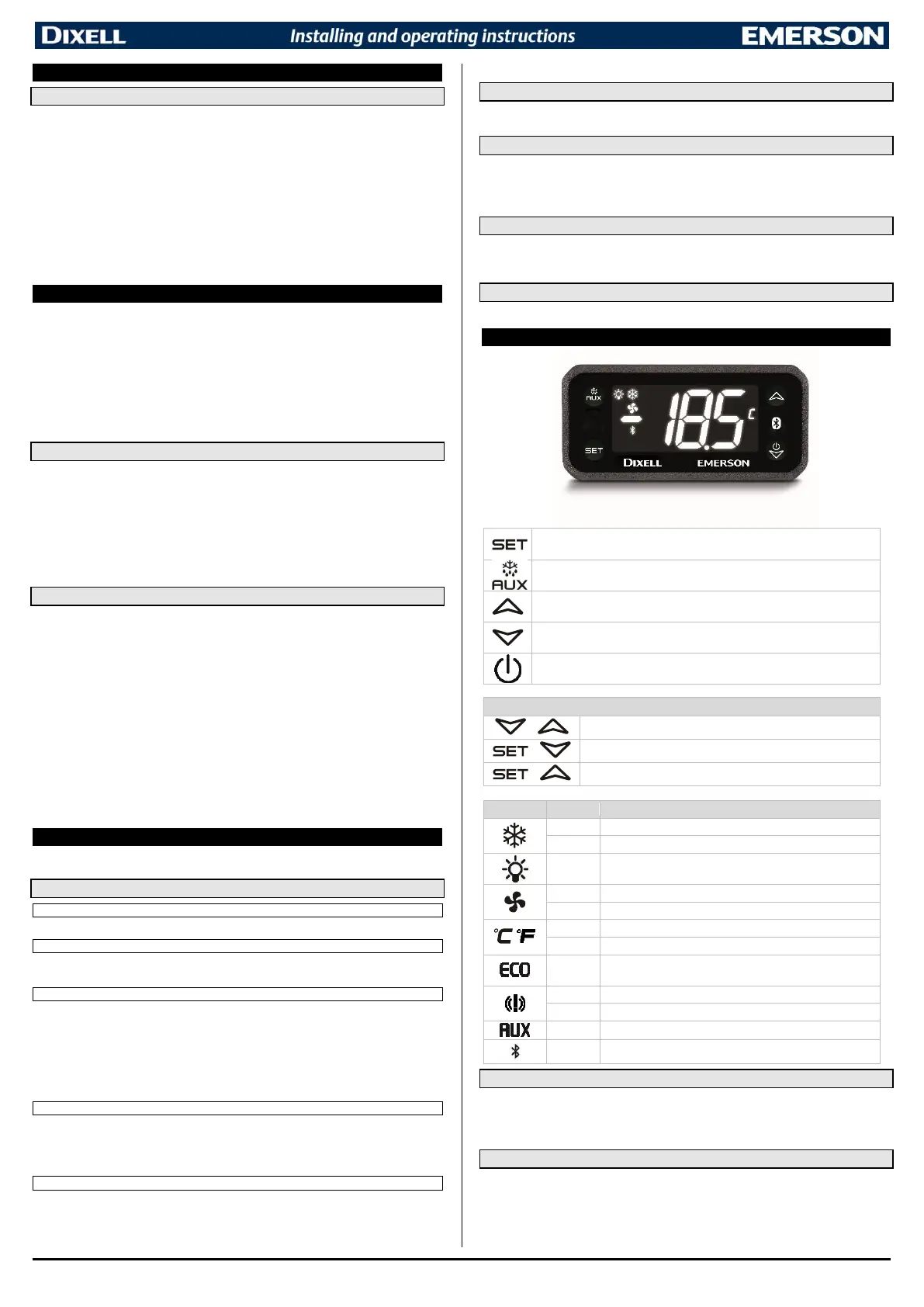
11 FRONT PANEL COMMANDS

 Loading...