1592034020 XR77CHC EN r1.0 2019.01.31 XR77CHC 5/7
Period to switch from normal mode to energy saving mode (valid if ErA=bAS): (0.0 to
24h00min, res. 10 min) if door stay closed for StE time, the energy saving mode will be
activated. NOTE: this will require a door switch to work.
Period to switch from energy saving mode to normal mode (valid if ErA=bAS): (0.0 to
24h00min, res. 10 min) maximum time for energy saving mode. NOTE: this will require a door
switch to work.
Door open time to switch from EtS to StE (valid if ErA=bAS): (0 to 999 sec) the energy
saving mode will be immediately deactivated as soon as the door stay open more than the dS
time. NOTE: this will require a door switch to work.
Number of relay output 1 activations (thousands of) (read only)
Number of relay output 1 activations (hundreds of) (read only)
Number of relay output 2 activations (thousands of) (read only)
Number of relay output 2 activations (hundreds of) (read only)
Number of relay output 3 activations (hundreds of) (read only)
Number of relay output 3 activations (hundreds of) (read only)
Number of relay output 4 activations (thousands of) (read only)
Number of relay output 4 activations (hundreds of) (read only)
Number of daily activations of digital input 1 (read only)
Number of digital input 1 activations (thousands of) (read only)
Number of digital input 1 activations (hundreds of) (read only)
Number of daily activations of digital input 2 (read only)
Number of digital input 2 activations (thousands of) (read only)
Number of digital input 2 activations (hundreds of) (read only)
Number of working hours for relay output oA1 (thousands of) (read only)
Number of working hours for relay output oA1 (hundreds of) (read only)
Number of working hours for relay output oA2 (thousands of) (read only)
Number of working hours for relay output oA2 (hundreds of) (read only)
Number of working hours for relay output oA3 (thousands of) (read only)
Number of working hours for relay output oA3 (hundreds of) (read only)
Number of working hours for relay output oA4 (thousands of) (read only)
Number of working hours for relay output oA4 (hundreds of) (read only)
REAL TIME CLOCK MENU - rtC
Day of the week: Sun to Sat
Day of the month: 1 to 31
First day of the weekend: (Sun to Sat; nu) set the first day of the week which follows
the holiday times.
Second day of the weekend: (Sun to Sat; nu) set the second day of the week which
follows the holiday times.
Working day energy saving starting time: (0 to 23h50min) during the Energy Saving
cycle the set point is increased by the value in HES so that the operation set point is
SET+HES.
Working day energy saving duration: (0 to 24h00min) sets the duration of the Energy
Saving cycle on workdays.
Holyday energy saving starting time: 0 to 23h50min.
Holyday energy saving duration: 0 to 24h00min.
Daily defrost enabled: (n; Y) to enable the Ld1…Ld6 defrost operations for any day of
the week.
Daily defrost starting time: (0 to 23h50min) these parameters set the beginning of the
6 programmable defrost cycles during workdays. Ex: when Ld2=12.4 the second defrost
starts at 12.40 during workdays.
N.B.: To disable a defrost cycle set it to “nu” (not used). Ex: if Ld6=nu; the sixth defrost cycle will be disabled.
BLUETOOTH - bLE
Bluetooth Mode: (0; 1; 2) define the pairing&bonding method:
- 0=6-digit PIN is required for pairing&bonding
- 1,2=no PIN required (just works mode)
Reset owner password: (n;Y) select and confirm YES to come back to default factory
configuration. NOTE: remember to cancel the device also from the Cloud database (click on
“Delete” link present on the right of the appliance card present on the “Permissions” webpage.
Reset whitelist: (n;Y) select and confirm YES for reset the device whitelist and come back to
default factory configuration.
Reset Daily Counters: used to reset the daily counters memory. Please note that after
selecting rSC=Y the device will take some time to complete the operation. During the reset
phase, the display will show some blinking lines.
Serial address: (1 to 247) device address for Modbus communication
Baudrate: (9.6; 19.2; 38.4; 57.6) select the correct baudrate for serial communication
Keyboard lock type: (nu; SEL; ALL) UnL=keyboard unlocked; SEL=only SET and DEF/AUX
button enabled when locked; ALL=keyboard unlocked after tLC.
Keyboard lock timeout: (0 to 255 sec) timeout after power-on and before activating the
keyboard lock
Light button configuration (left upper side): nu=not used; LiG=light output control;
AUS=auxiliary output control; dEF=defrost control; Pb2=probe 2 value visualization;
ES=change working mode from normal to energy saving mode and vice-versa;
Light button timed (3sec) configuration (left upper side): nu=not used; LiG=light output
control; AUS=auxiliary output control; dEF=defrost control; CC=change configuration between
NT and LT map; ES=change working mode from normal to energy saving mode and vice-versa;
Up button timed (3sec) configuration: nu=not used; Std=standard function; LdC=load
default configuration (factory values); Pdn=pull down activation
Probe P1 value visualization
Probe P2 value visualization
Probe P3 value visualization
Probe P4 value visualization
Firmware release date: day
Firmware release date: month
Firmware release date: year
Firmware release: progressive number
Firmware sub release: progressive number
14 DIGITAL INPUTS
The free voltage digital input is programmable in different configurations by the i1F and i2F.
DOOR SWITCH (ixF=dor)
It signals the door status and the corresponding relay output status through the odC parameter:
no = normal (any change); FAn = Fan OFF; CPr = Compressor OFF; F-C = Compressor and fan OFF.
Since the door is opened, after the delay time set through parameter did, the door alarm is enabled,
the display shows the message “dA” and the regulation restarts if rrd = Y. The alarm stops as soon
as the external digital input is disabled again. With the door open, the high and low temperature alarms
are disabled.
START DEFROST (ixF=dEF)
It starts a defrost if there are the right conditions. After finishing any defrost, the normal regulation will
restart only if the digital input is disabled, otherwise the instrument will wait until the MdF safety time is
expired.
ENERGY SAVING (ixF=ES)
The energy saving mode will be enabled / disabled with the digital input.
MOTION SENSOR (ixF=EMt)
It counts the motion sensor detections.
AUXILIARY OUTPUT (ixF=AUS)
The AUX output (if present and configured) will be enabled / disabled with the digital input.
EXTERNAL WARNING ALARM (ixF=EAL)
It is used to detect an external alarm. It does not lock the regulation.
EXTERNAL LOCK ALARM (ixF=bAL)
It is used to detect any critical external alarm. It locks immediately the regulation.
EXTERNAL PRESSURE ALARM (ixF=PAL)
It is used to detect any pressure external alarm. This signal locks the regulation after nPS events in
dxd interval od time.
EVAPORATOR FAN MODE (ixF=FAn)
It is used to control the evaporator fan.
REMOTE HOLYDAY MODE (ixF=HdF)
It is used to force the holyday mode.
REMOTE ONOFF (ixF=onF)
It is used to switch ON and OFF the device remotely.
LIGHT OUTPUT (ixF=LiG)
It is used to control the light output.
CHANGE CONFIGURATION (ixF=CC)
It is used to change the controller configuration.
MOTION SENSOR DETECTOR (ixF=EMt)
To use the X-MOD motion sensor. Please note that motion sensor can be connected only to the
HOTKEY port, so it needs digital input 2 properly configurated.
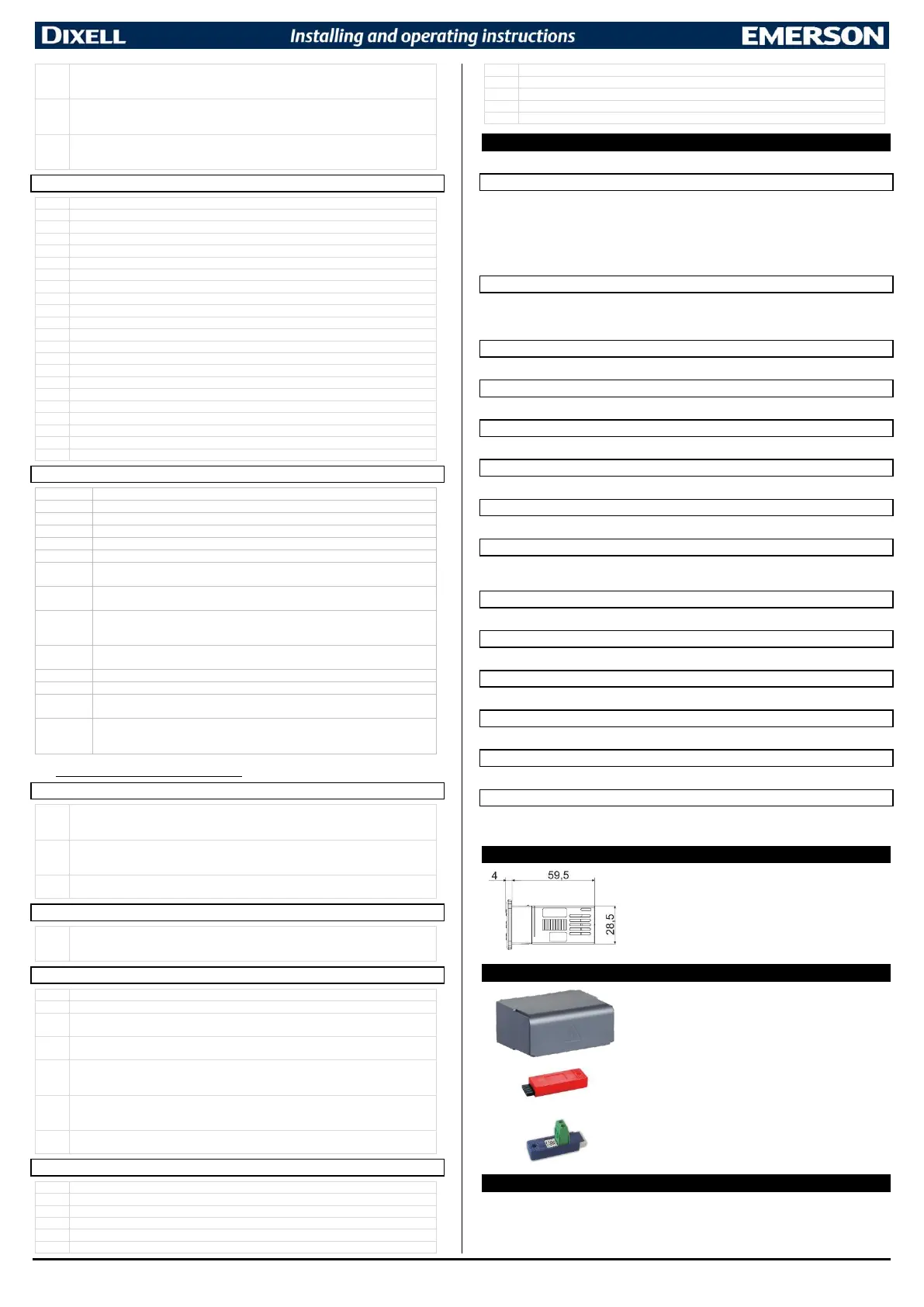
15 INSTALLATION AND MOUNTING
Instrument XR77CHC shall be mounted on vertical panel, in a
29x71 mm hole, and fixed using the special bracket supplied.
The temperature range allowed for correct operation is 0 to 60°C.
Avoid places subject to strong vibrations, corrosive gases,
excessive dirt or humidity. The same recommendations apply to
probes. Let air circulate by the cooling holes.
The MDP/CX rear cover can be used to increase the protection
from water and dust.
The HOT-KEY is used for a quick and easy upload (from device
to HOT-KEY) or download (from HOT-KEY to device) the
parameter map.
The XJ485LE serial interface converts the TTL output into an
RS485 signal that can be used to connect the unit to the
controlling and supervising system. Please note that other
version of this converter does not work with XR-CHC devices.
17 ELECTRICAL CONNECTIONS
The instrument is provided with screw terminal block to connect cables with a cross section up to
2.5mm
2
. Before connecting cables make sure the power supply complies with the instrument’s
requirements. Separate the probe cables from the power supply cables, from the outputs and the

 Loading...