1592020670 XRi77CX-CH GB r1.1 15.10.2019 XRi77CX-CH 6/9
14.5 SWITCH THE AUXILIARY RELAY (IXF = AUS)
With oAx=AUS the digital input switched the status of the auxiliary relay.
14.6 INVERSION OF THE KIND OF ACTION: HEATING-COOLING (IXF = HTR)
This function allows inverting the regulation of the controller: from cooling to heating and viceversa.
14.7 ENERGY SAVING (IXF = ES)
The Energy Saving function allows to change the set point value as the result of the [SET+HES]
(parameter) sum. This function is enabled until the digital input is activated.
14.8 ON OFF FUNCTION (IXF = ONF)
To switch the controller on and off.
14.9 CHANGE PARAMETER MAP (IXF = NT)
To move from LT to NT parameter map.
14.10 DIGITAL INPUTS POLARITY
The digital input polarity depends on the i1P and i2P parameters.
• i1P or i2P=CL, the input is activated by closing the contact.
• i1P or i2P=OP, the input is activated by opening the contact.
15. RS485 SERIAL LINE – FOR MONITORING SYSTEMS
The RS485 serial line allows connecting the instrument to a monitoring system (ModBUS-RTU
compatible).
16. INSTALLATION AND MOUNTING
Instrument XRi77CX-CH shall be mounted on vertical panel, in a
29x71 mm hole, and fixed using the special bracket supplied.
The temperature range allowed for correct operation is 0 to 60°C.
Avoid places subject to strong vibrations, corrosive gases,
excessive dirt or humidity. The same recommendations apply to
probes. Let air circulate by the cooling holes.
17. ELECTRICAL CONNECTIONS
The instrument is provided with screw terminal block to connect cables with a cross section up to
2.5mm2. Before connecting cables make sure the power supply complies with the instrument’s
requirements. Separate the probe cables from the power supply cables, from the outputs and the
power connections. Do not exceed the maximum current allowed on each relay, in case of heavier
loads use a suitable external relay.
17.1 PROBE CONNECTION
The probes shall be mounted with the bulb upwards to prevent damages due to casual liquid infiltration.
It is recommended to place the thermostat probe away from air streams to correctly measure the
average room temperature. Place the defrost termination probe among the evaporator fins in the
coldest place, where most ice is formed, far from heaters or from the warmest place during defrost, to
prevent premature defrost termination.
18. HOW TO USE THE HOT KEY
To enable the HOT-KEY port (5-pin connector), set the par. oAn=n.
18.1 PROGRAM A HOT KEY FROM AN INSTRUMENT (UPLOAD)
1. Program one controller with the front keypad.
2. When the controller is ON, insert the “HOT-KEY” and push UP button; the “uPL” message
appears followed a by a flashing “End” label.
3. Push SET button and the “End” will stop flashing.
4. Turn OFF the instrument, remove the “HOT-KEY” and then turn it ON again.
NOTE: the “Err” message appears in case of a failed programming operation. In this case push again
button if you want to restart the upload again or remove the “HOT-KEY” to abort the operation.
18.2 PROGRAM AN INSTRUMENT BY USING A HOT KEY (DOWNLOAD)
1. Turn OFF the instrument.
2. Insert a pre-programmed “HOT-KEY” into the 5-PIN receptacle and then turn the Controller
ON.
3. The parameter list of the “HOT-KEY” will be automatically downloaded into the Controller
memory. The “doL” message will blink followed a by a flashing “End” label.
4. After 10 seconds the instrument will restart working with the new parameters.
5. Remove the “HOT-KEY”.
NOTE: the message “Err” is displayed for failed programming. In this case turn the unit off and then
on if you want to restart the download again or remove the “HOT-KEY” to abort the operation.
19. ALARM SIGNALS
Compressor output works with Con and CoF
Maximum temperature alarm
Minimum temperature alarm
Condenser high temperature
It depends on the AC2 parameter
Condenser low temperature
It depends on the bLL parameter
Serious external alarm (ixF=bAL)
Real time clock parameter error
Output unchanged, defrost follows idF, need to
set RTC parameters
Real time clock malfunctioning
Output unchanged, defrost follows idF
19.1 BUZZER MUTING OR ALARM RELAY OUTPUT DEACTIVATION
If tbA=Y, the buzzer and the relay are silenced by pressing any key.
If tbA=n, only the buzzer is silenced while the alarm relay is on until the alarm condition recovers.
19.2 ALARM RECOVERY
Probe alarms “P1”, “P2”, “P3” and “P4” start some seconds after the fault in the related probe; they
automatically stop some seconds after the probe restarts normal operation. Check connections before
replacing the probe.
Temperature alarms “HA” and “LA” automatically stop as soon as the temperature returns to normal
values.
Alarms “EA” and “CA” (with i1F=bAL) recover as soon as the digital input is disabled.
19.3 OTHER MESSAGES
In programming mode: no parameter in Pr1.
On the display or in dP2, dP3, dP4: the selected probe is not enabled.
20. TECHNICAL DATA
Housing: self-extinguishing ABS
Case: frontal 32x74mm; depth 60mm
Mounting: panel mounting in a 71x29mm panel cut-out
Protection: IP20
Frontal protection: IP65
Connections: Screw terminal block 2.5 mm
2
wiring
Power supply: (according to the model) 230Vac 10%, 50/60Hz; 110Vac 10%, 50/60Hz
Power absorption: 3VA max
Display:
- 3 digits, red LEDs, 14.2 mm high (CX format)
- 3 digits, red LEDs, 19 mm high (CH format)
Inputs: Up to 4 NTC, PTC or PT1000 probes
Digital inputs: free voltage contact
Frequency output: 30 to 200 Hz, 14Vdc MAX, duty cycle=50%
Relay outputs (nominal ratings):
- oA1: SPST 16(5)A 250Vac
- oA2: SPDT 8(3)A, 250Vac
- oA3: SPST 5(2)A, 250Vac
- oA4: SPST 8(3)A 250Vac
Data storing: on the non-volatile memory (EEPROM)
Internal clock back-up: 24 hours
Kind of action: 1B
Pollution degree: 2
Software class: A
Rated impulsive voltage: 2500V; Overvoltage Category: II
Operating temperature: 0 to 55°C (32 to 131°F)
Storage temperature: -30 to 85°C (-22 to 185°F)
Relative humidity: 20 to 85% (no condensing)
Measuring and regulation range:
- NTC probe: -40 to 110°C (-40 to 230°F)
- PTC probe: -50 to 150°C (-55 to 302°F)
- PT1000 probe: -100 to 150°C (-148 to 392°F)
Resolution: 0.1°C or 1°C or 1°F (selectable)
Accuracy (ambient temp. 25°C): ±0.7°C ±1 digit
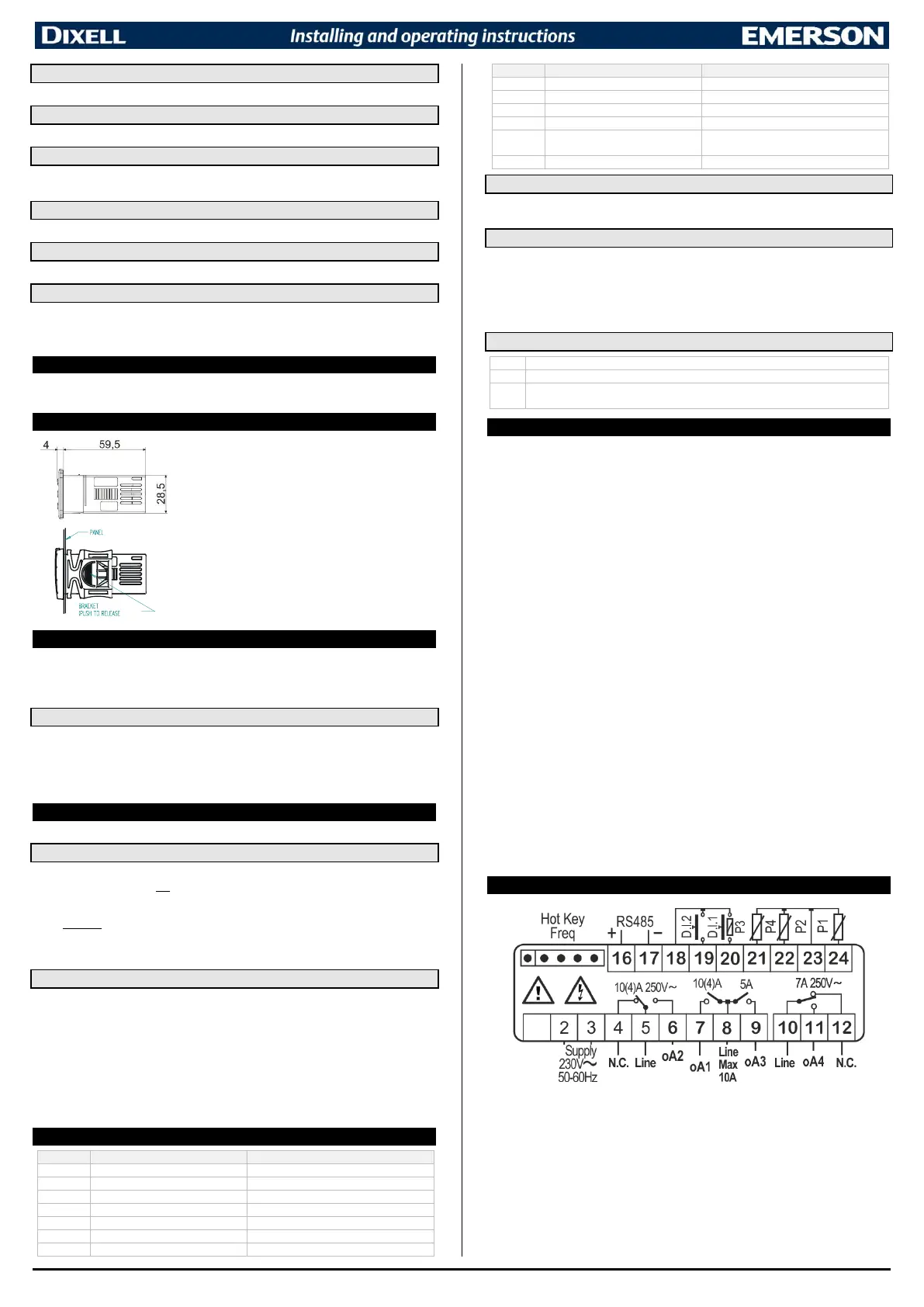
21. WIRINGS

 Loading...


