EC1-233_65150_EN_R02.doc Replacement for R01 2 / 2 Part No. 864 908 07.07.2008
EC1-233 Display Case and Coldroom Controller
Operating Instructions
GB
Parameter Modification: Procedure
• When the Prg LED is illuminated the parameters may be modified and the first
parameter “St” will be displayed.
• Press the Prg button again to display the current value associated with the
parameter.
• Press
or to increase or decrease the value. Pressing either button for 3
seconds will increase the speed of value change.
• Press the Prg button again to display the current parameter; “St”
• Press
repeatedly to show the next parameter code to be changed;
• Press the Prg button again to display the current value associated with the
parameter and the
or to increase or decrease the value.
• Repeat the procedure from the beginning "press
repeatedly to show..."
To exit and save the new settings:
• Press Prg for 3 seconds to confirm the new values and exit the parameters
modification procedure. The Prg LED will be turned off.
• Alternatively avoid pressing any button for at least 15 seconds and the controller
will automatically revert to the operation mode; controller “times out”.
• If any parameter is modified and the controller then times out, the new setting
will be automatically saved.
Copy Key Procedure
Upload procedure:
• With the controller powered, plug the copy key into the mini USB.
• Press the
button and the controller will display “UPL”.
• Press the PRG button to start the upload process to the copy key.
• Turn 230V power off before removing the copy key from the controller.
Download procedure:
• Turn 230V power off before inserting the copy key into the controller.
• Turn 230V power on. The controller will automatically detect the copy key is
present and start downloading the stored parameters into the controller. “DOW”
will be displayed on the controller during downloading process.
• Turn 230V power off before removing the copy key from the controller or the
data will be corrupted.
• Turn 230V power on and check the parameter values following the parameter
modification procedure above.
Caution:
DO NOT turn the controller off during this process. The control temperature will
be displayed when the process has been completed. ”Err” will be displayed if there
is an error during the upload/download procedure.
Any attempt to download a second set of parameter into the copy key will
automatically overwrite the original set.
Defrost Activation:
A defrost cycle can be activated locally from the keypad:
• Press the button for more than 3 seconds, the defrost cycle is activated and
the defrost LED will be illuminated (only if S5< value of parameter dt).
Continuous Cooling Demand Activation:
The controller can be set to continuous cooling:
• Press
the button for more than 3 seconds, the controller will be forced into the
cooling mode and the cooling LED will be illuminated.
• Press
the button for more than 3 seconds again to stop the continuous cooling
process.
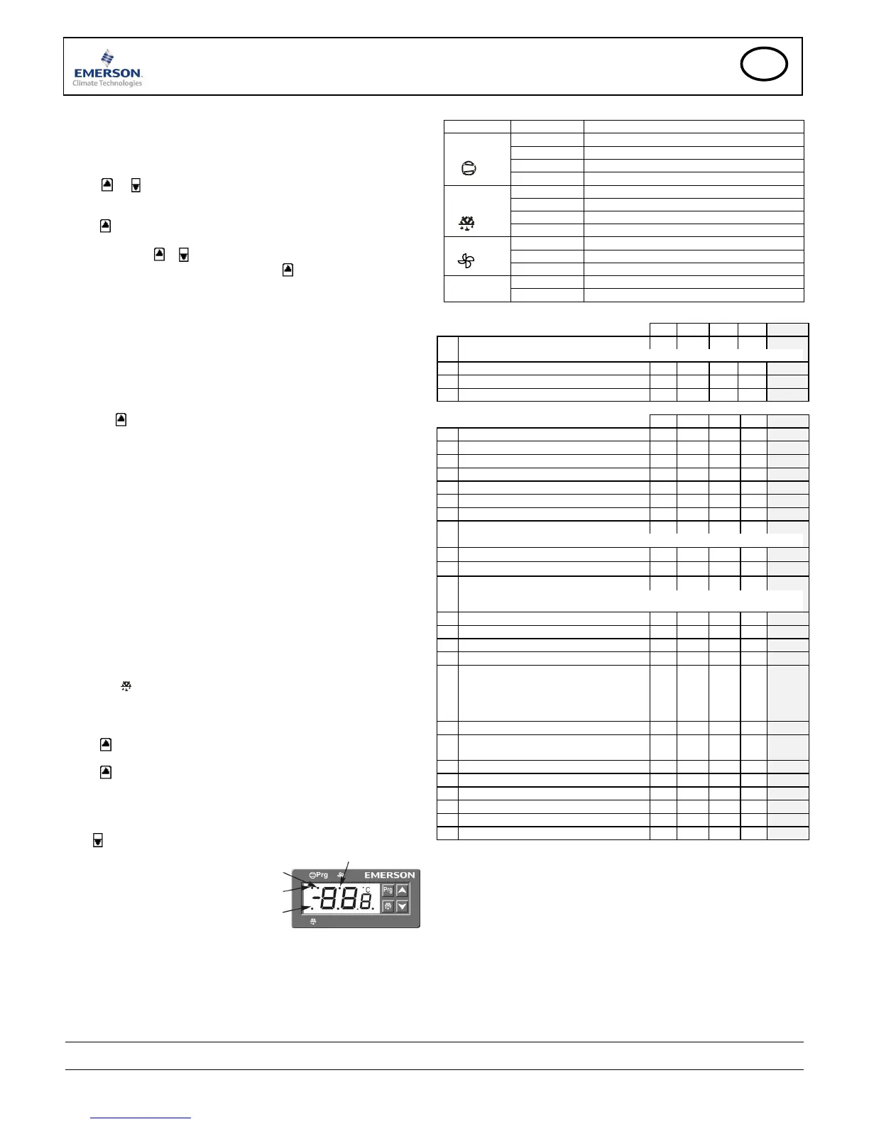
Display of Data:
During normal operation, the display will show the temperature measured by the
S1 air sensor.
Press
to display the current value associated with the defrost termination sensor.
LED displayed when:
Parameter alteration mode is active.
Compressor / Cooling relay active
Defrost heater relay active
Fan relay active
Note: A blinking LED indicates the respective relay is inhibited from becoming
active due to a time delay or an active alarm condition
LED Indication
Indicator Status Function
OFF Cooling relay inactive: cooling off
Blinking Compressor start delay
ON Cooling relay active: cooling on
Cooling
Blinking: fast Cooling relay active: continuous cooling
OFF Defrost relay inactive: defrost off
ON Defrost relay active: defrost on
Blinking Defrost relay inactive: drain down
Defrost
Blinking: fast Defrost relay active: forced defrost
OFF Fan relay inactive: fan off
Blinking Fan start delay
Fan
ON Fan relay active: fan on
OFF Normal working mode
Prg
ON Controller in programming mode
List of Parameters
USER
Min Max Unit Def.
Custom
St Temperature control setpoint r1 r2 °C -5.0
cut in = set-point + difference; cut out = set-point
rd Control deadband differential 1.0 +25.0 K 2.0
dP Max defrost duration 0 255 min 30
dI Defrost interval (0.1 h = 6 min.) 0.0 99.9 h 6.0
Factory default settings are all in °C. Refer to parameter /5 for °F settings
ADMINISTRATOR
Min Max Unit Def.
Custom
r1 Minimum setpoint -45.5 St °C -20.0
r2 Maximum setpoint St 110 °C 20.0
/C Air temperature alignment for S1 -10.0 +10.1 K 0.0
/d Defrost temperature alignment for S5 -10.0 +10.1 K 0.0
C2 Compressor start delay time 0 50 min 3
C3 Minimum emergency RUN time 0 255 min 45
C4 Maximum emergency OFF time 0 255 min 15
/5 Temperature Unit °C °F - °C
Note: When /5=°F all temperature parameters must be entered in °F or Rankin
d0 Defrost type: EL = electric; HtG = off cycle EL
dt Defrost termination temperature -45.5 +49.9 °C 10
/7 Display during defrost rt
rt: Air temperature (S1)
lt: Defrost start-up temperature
SEt: Air setpoint temperature
dEF: “dEF” displayed
A3 Display delay after defrost 0 255 min 30
d7 Drain down time: cooling restart delay 0 255 min 2
d4 Defrost at start-up y = yes, n = no n
d5 Defrost delay after start-up 0.0 24.0 h 0.0
F1 Fan mode:
C-n: start/stop with cooling, Off during defrost
O-n: continuously on, Off during defrost
C-Y: start/stop with cooling, ON during defrost
O-Y: continuously on, ON during defrost
C-n
Fd Fan delay after defrost 0 255 min 10
Ft On temp differential after defrost
Diff: Air temp. (S1) – Defrost temp. (S5)
0.0 +50.0 °C 10.0
AH
High temp alarm limit AL 110 °C 110
AL Low temp alarm limit -45.5 AH °C -45.5
A1 Air temp alarm delay 0 255 min 15
A2 Air temp. alarm delay after start-up 0 255 min 60
Ert Temperature sensor failure delay 0 255 min 0
FSt Fan stop temperature setpoint -45.5 +49.9 °C 10.0
Alarm Codes
AH High temperature alarm
Upper control temp alarm limit (AH) exceeded beyond delay time (A1)
AL Low temperature alarm
Lower control temperature alarm limit (AL) exceeded beyond delay time
(A1)
Er Sensor error
Air or defrost sensor open circuit
Compressor run & off times are set by parameters C3 and C4
Emerson Electric GmbH & Co OHG is not to be held responsible for erroneous
literature regarding capacities, dimensions, applications, etc. stated herein.
Products, specifications and data in this literature are subject to change without
notice. The information given herein is based on technical data and tests which
ALCO CONTROLS believes to be reliable and which are in compliance with
technical knowledge of today. It is intended only for use by persons having the
appropriate technical knowledge and skills, at their own discretion and risk. Since
conditions of use are outside of ALCO'S control we cannot assume any liability for
results obtained or damages occurred due to improper application.
This document replaces all former versions
Emerson Electric GmbH & Co OHG - Postfach 1251 - Heerstraße 111 - 71332 Waiblingen - Germany - Phone +49 7151 509 0 - Fax +49 7151 509 200
www.emersonclimate.eu

 Loading...


