Emerson Climate Technologies GmbH www.emersonclimate.eu
Am Borsigturm 31 I 13507 Berlin I Germany Date: 07.12.2015 EXD-U01_OI_ML_R02_865910.docx
General information:
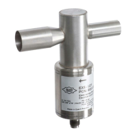
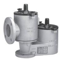
EXD-U01 Universal Driver Module is for driving Emerson stepper motor driven
electrical control valves series EX4…EX8 / CX4…CX7.
Safety instructions:
• Read operating instructions thoroughly. Failure to comply can result in
device failure, system damage or personal injury
• According to EN 13313 it is intended for use by persons having the
appropriate knowledge and skill.
• Before wiring disconnect all voltages from system and device.
• Do not operate system before all cable connections are completed.
• Do not apply 110/220/230V to any terminal of driver module
• Entire electrical connections have to comply with local regulations.
Installation and wiring
• Install electrical control valve in system according to operating instructions of
valve.
• Install Driver Module and other external electronic devices as shown in wiring
diagram (see Fig. 2).
• Keep separate the wires for power supply, stepper motor of valve and signal.
• Recommended wire size Ø 0.5 … 2.5 mm
2
.
Setting (Fig.1):
• Disconnect voltage
• Set dip switches as per table below
Startup procedure:
• The valve must be closed before system charging in case of expansion valve or
hot gas bypass function. The valves are delivered at half open position.
Valve closure:
• Remove 24 V from digital input.
• Apply supply voltage to driver for the minimum time in below table: (valve
motor makes a characteristic sound until it reaches the closed position)
• After closure of valve evacuate the entire system.
• Then charge the system with refrigerant.
• Turn on digital input (24V)
• Start the system and check operating conditions.
Valve Synchronization:
• After power up EXD-U01 synchronizes the stepper motor driven valve with the
reference point in the fully closed position.
Technical data, power supply:
• Main supply voltage: 24 VAC ±10%, 50-60 Hz (use 1.0 A external fuse).
Note: 24 VDC supply voltage can be used but it results to lower MOPD and it
needs to be verified by system manufacture.
• Use a safety class II transformer.
Minimum power required 20 VA.
• Emergency supply voltage Ub (from ECP-024): +18 VDC.
Inputs:
• 1 analog input 4…20 mA, burden 364 Ω, or
1 analog input 0…10 V, impedance 27 kΩ.
1 digital input: 24 VAC/DC (+10%, -15%), 50-60 Hz.
Outputs:
• 4 current outputs for stepper motor of EX4…EX8/ CX4…CX7.
Uninterruptible power supply ECP-024
• Power supply voltage: 24 VAC ± 10%
• Power outputs: two, each +18 VDC
Wiring Diagram (see Fig. 2)
(1) = Supply voltage
(2) = Transformer
(3) = Fuse 1.0 A
(5) = Plug cable assembly EXV-Mxx for connection to EX4…EX8 / CX4…CX7
Cable color code
WH = White BK = Black
BL = Blue BN = Brown
(6) = Controller supplies 4…20 mA or 0…10 V
(7) = Digital input signal (0 V = OFF; 24 V = ON)
(8) = Analog input signal (4…20 mA or 0…10 V)
(9) = Optional Uninterruptible Power Supply insures the closure of valve during
power failures in systems, where a valve with positive shut-off function is
needed
• Marking: ,