2
EFFECTIVE OIL PRESSURE
Effectivenetoilpressureisthedifferencebetweentheoilpump
outletpressureandthecompressorcrankcasepressure.
EXAMPLE:
Oil Pump Outlet Pressure 40PSIG 20PSIG
Crankcase Pressure 10PSIG 8’’vacuum
Net Effective Oil Pressure 30PSIG 24PSIG
TheFD113measuresthedifferentialpressurebetweentheoil
pumpoutletpressureandthecompressorcrankcasepressure.
TheFD113–ZU/ZUKisfactorypresetto—
Pressure Energize Timer:10PSIDonfallingpressure
De–Energize Timer:15PSIDonrisingpressure
Time–Lockoutafter120secondsofenergizedtime
(ThisisCopelandfactoryspecications)
Manufacturer’s Setting Specications (Typical)
Low Event PSID
Manufacturer Time Delay(seconds)
➀
(EnergizetimeronfallingPSID)
Copeland 120 9–10*
Bitzer 90 9–10*
Carrier 45 6.5**
* Standardfactorysetting–9/10PSIDLowEvent.Noadjustmentrequired.
** Requiresadjustmentapproximately1/2turntoleftper“Checkingand
AdjustingPressure”instructions.
➀ Standardfactorysetting120seconds(Copeland).Adjustasrequiredto
othermanufacturer’sspecications.Seegure1“TimerAdjustment
Button”–Verifytimingutilizingeither“CheckingandAdjustingTimer”
procedureor“ControlCheckout/TimerCheckout”procedureandreadjust
asrequired.
NOTE: After pressure and time settings have been made and veried, a
piece of tape should be placed over the pressure setting disc slot
and timer adjustment button to prevent tampering.
(Reference gure 1)
CONTROL CALIBRATION/ADJUSTMENT
Pressure Check—BENCH TEST NO VOLTAGE APPLIED
1) Attach“Oil”connectiontopressuresource
(100PSIGMax)withalowpressuregauge.
2) Leave“Low”connectionatatmosphericpressure
(unattached).
3) ConnectContinuityTesterbetweenterminals11
and14(safelightconnection).Nocontinuityshould
beshown.
4) Pressurizeoilconnectionto100PSIG.
Continuitylightshouldenergize.
5) Slowlydepressurize.Continuitylightshouldde-energize
atapproximately10PSIG(factory).
6) Slowlyre-pressurize.Continuitylightshouldre-energize
approximately5PSIabovede-energizepressure.
Pressure Adjustment—
1) Tochangepressureadjustmentfromfactorysetting,
removecontrolcover.Rotatenotchedpressuresetting
discinthecontrol–righttoincrease,lefttodecrease
settings(seegure1).Repeatsteps4-6todetermine
settings.Adjust/Repeatasnecessarytoobtaindesired
timerstart(minimumoilpressuresetting).Note:Control
shouldnotbesettobelowminimumeffectiveoilpressure
recommendedbythecompressormanufacturer.
CHECKING AND ADJUSTING PRESSURE
Thetimerisfactorypresetto120seconds
(CopelandSpecication).
Timer Checkout
1) RemoveJumperbetween11&22.
2) Connectacontinuitylightacrossterminals21and24.
Nocontinuityshouldbeshown(ifitdoes,press
resetbutton).
3) Withnopressuretothe“Oil”or“Low”bellows
connections,apply24to240VoltAC/DCacross
terminals11and“N”.Thetimershouldtripoutand
continuityshouldstartbetweenterminals21and24
afterapproximately120seconds.
Timer Adjustment
1) Removepowerfromterminals11and“N”.Pushreset
button,adjusttimerbuttontotimedesired.
2) Re–energizeterminals11/“N”,observetimetotrip–out
(continuitybetweenterminals21and24).
3) Repeatsteps1and2untildesiredtrip–outtimeis
obtained.NOTE:Controlshouldnotbesetbelowthe
minimumtimespeciedbythemanufacturer.
4) Removepowerandcontinuitylightandreinstall11/22
Jumper,ifrequired.
CHECKING AND ADJUSTING TIMER
Penn Ranco Robertshaw To ALCO Terminal
L L L 21
M M M 22
(Alarmwhenpresent) A S 24
V/V1 AorB
120 120 120 N
240 240 240
2 2 T2 11
None None None 14“Normal”light
Pressure Connections
1) Withthecompressordepressurized(0PSIG),connect
thebottompowerelementmarked“Oil”totheoil
pumpoutletconnection.
2) Connectthetoppowerelementmarked“Low”tothe
compressorcrankcaseconnection.
Electrical Wiring
1) WhenreplacingaRanco,Penn,orRobertshawcontrol,
usethefollowingwiringcrossreference.
FD113 INSTALLATION
ThewiringoftheFD113isillustratedingures4&5.
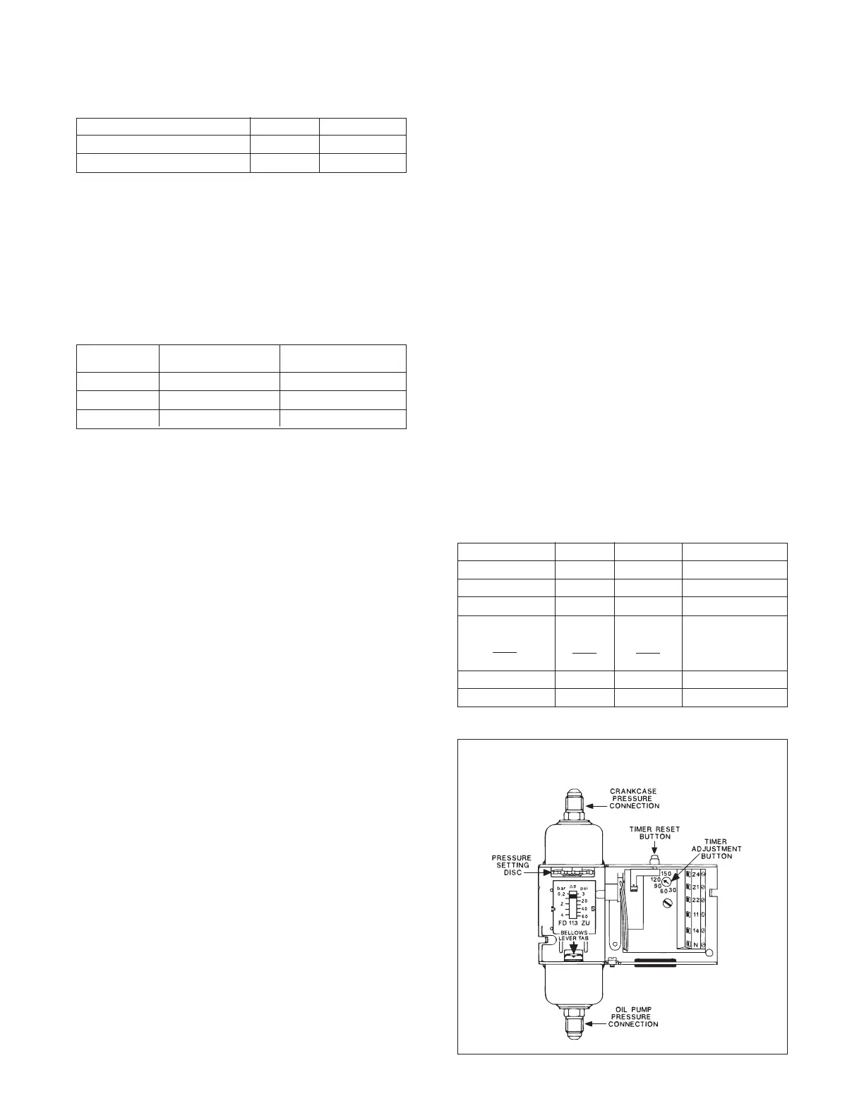
FIGURE 1—FD113 WITH COVER OFF

 Loading...


