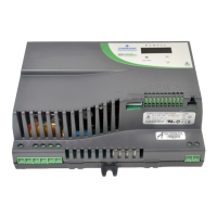
Do you have a question about the Emerson FPCSK and is the answer not in the manual?
Crucial warnings about installation, wiring, and handling to prevent hazards.
Welcome and overview of the Electronic bypass package and manual.
Verifies part numbers, checks for shipping damage, and ensures internal hardware is secure.
Details the two nameplates for identification and the information they contain.
Explains how to identify product part numbers based on a coding system.
Provides guidelines for physical installation, including required clearances for heat dissipation.
Outlines general wiring practices and critical safety precautions during installation.
General safety rules for wiring, including not connecting/disconnecting while powered.
Covers input wiring options and recommendations for connecting power supply.
Details the output wiring options and recommended conduit locations for motor connections.
Describes analog output, digital inputs, and relay outputs for FPCSK models.
Details analog output, digital inputs, and relay outputs for FPCBA models.
Provides instructions for proper grounding procedures, emphasizing separate conduits.
Checklist for verifying wiring completion, cleanliness, and secure fastenings.
Procedures for verifying correct motor rotation in VFD and Bypass modes.
Step-by-step guide to check motor rotation while operating on VFD power.
Guide to check motor rotation when operating on bypass power.
Describes the control board, DIP switches, and jumper settings for configuration.
Overview of the keypad buttons, LEDs, and their functions for operation.
Explains the function of four configuration switches for tailoring bypass behavior.
Details additional customer inputs like Safety, Remote Bypass, and Remote VFD.
Lists the alarms that can be displayed, including motor overload and VFD faults.
Explains how the system handles control card failure and power loss.
Outlines the different operational modes: TEST, VFD, HAND, AUTO.
Describes the TEST mode for setting up and reading system characteristics.
Explains the VFD mode where input and output contactors are energized.
Details the BYPASS mode where the bypass contactor is energized.
Covers HAND mode for local control via keypads and pushbuttons.
Explains AUTO mode for remote control via building automation systems.
Describes three modes for bypassing the VFD and using full line power.
Explains manual bypass operation, initiated by HAND or AUTO mode selection.
Details automatic bypass activation upon sensing a VFD fault.
Describes emergency bypass activation via a jumper for control board failure.
Lists essential parameters for Commander HSK for proper bypass package operation.
Lists essential parameters for Affinity BA for proper bypass package operation.
Recommended parameters for Commander HSK during start-up, based on application.
Recommended parameters for Affinity during start-up, based on application.
Crucial safety and operational guidelines to prevent damage and injury.
Explains how to use the VFD and Electronic Bypass keypads for control.
Details the VFD keypad's primary use for speed control and monitoring.
Describes the Electronic Bypass keypad's role in controlling the package.
Breaks down the Electronic Bypass keypad into its four main sections.
Explains the five system status LEDs indicating power, operation mode, and run status.
Describes the three buttons for selecting the start mode (HAND, AUTO, OFF/RESET).
Details the three buttons for selecting the operation mode (TEST, VFD, BYPASS).
Lists the four alarm LEDs indicating specific faults like Motor Overload or VFD Fault.
Two-step process for initiating operation: selecting mode and start mode.
Two options for ending operation: cancelling start mode or operation mode.
Details the four alarm LEDs on the keypad and their meanings.
Indicates a tripped motor overload relay and checks for proper settings.
Indicates an open external safety interlock, checking for jumpers or contact closure.
Signals a fire condition, affecting operation based on purge or stop mode.
Indicates a fault on the VFD, with codes displayed on the VFD keypad.
Lists technical specifications of the Electronic Bypass package.
Details design features, operating conditions, and approvals for the bypass.
Describes periodic maintenance and inspection procedures for the bypass.
A checklist for pre-power checks, control wiring, and power-up verification.
Checklist for VFD startup, including connections, settings, and motor nameplate data.
Wiring diagram for the FPCSK model of the Electronic Bypass Controller.
Wiring diagram for the FPCBA model of the Electronic Bypass Controller.
| Brand | Emerson |
|---|---|
| Model | FPCSK |
| Category | Controller |
| Language | English |


