Instruction Manual
D200126X012
2502 Controllers
June 2017
8
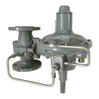
Figure 5. Cage Connection Styles
A1271-2
STYLE 1: TOP
AND BOTTOM
STYLE 2: TOP
AND LOWER SIDE
STYLE 3: UPPER
AND LOWER SIDE
STYLE 4: UPPER
SIDE AND BOTTOM
SCREWED: S3
FLANGED: F3
SCREWED: S2
FLANGED: F2
SCREWED: S1
FLANGED: F1
SCREWED: S4
FLANGED: F4
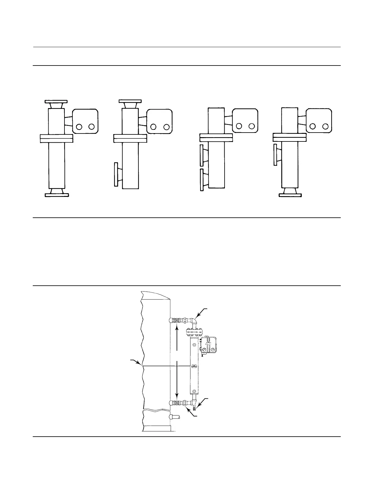
Mount the cage by running equalizing lines between the cage connections and the vessel (figure 6). A shutoff or hand
valve with a 1‐1/2 inch diameter or larger port should be installed in each of the equalizing lines. Also install a drain
between the cage and shutoff or hand valve whenever the bottom cage line has a liquid‐trapping low point.
On liquid or interface level applications, position the sensor so that the line marked FLOAT CENTER on the cage is
located as close as possible to the center of the liquid level or interface level range being measured. Also consider
installing a gauge glass either on the vessel, or on the sensor cage (if the cage is tapped for a gauge).
Figure 6. Caged Sensor Mounting
EQUALIZING LINE
DRAIN VALVE
EQUALIZING LINE
CENTER OF LIQUID
OR INTERFACE LEVEL
DF5379‐A
A1883‐2
SHUTOFF
VALVES

 Loading...