The vent assembly is equipped with a relief indicator (key 49,
Figure 4). The cap for the relief indicator snaps over the vent
assembly opening. If the relief valve opens wide, exhaust
gas pops the cap off the screen vent assembly opening
indicating a problem with the regulator. If the cap pops off,
refer to the shutdown and to the Body Area Maintenance
Procedures to inspect the disk assembly and orifice.
If the disk assembly and orifice are not damaged, refer to the
Diaphragm and Spring Case Area Maintenance Procedures
in this section.
The disk assembly and orifice can be inspected,
removed and replaced without removing the regulator
body from the line connections. Refer to the Body Area
Maintenance Procedures.
Body Area Maintenance Procedures
These procedures are for gaining access to the disk
assembly orifice, diaphragm casing O-ring and stem
assembly. All pressure must be released from the diaphragm
casing before performing these steps.
While using the following procedures, refer to
Figures 7 through 13 for key number locations.
Replacing the Disk Assembly or Orifice
1. To inspect and replace the disk assembly (key 9) or
orifice (key 2), remove the cap screws (key 3, Figure 5)
and separate the diaphragm casing (key 5) from the
body (key 1).
2. Inspect and, if necessary, remove the orifice (key 2). If
removed, coat the threads of the replacement orifice
with lubricant and torque to 25 ft-lbs / 34 N•m.
3. Inspect the disk assembly (key 9) and, if necessary,
remove the hair pin clip (key 13) that holds the disk
assembly (key 9) in place. If replacing the disk assembly
is the only maintenance required, skip to step 16.
Replacing the Stem Assembly
If it is necessary to perform maintenance on the stem
assembly, continue with steps 4 through 8 and 15 through 19
for Types 627, 627H, 627R and 627LR regulators or steps 9
through 19 for Types 627M, 627HM and 627MR regulators.
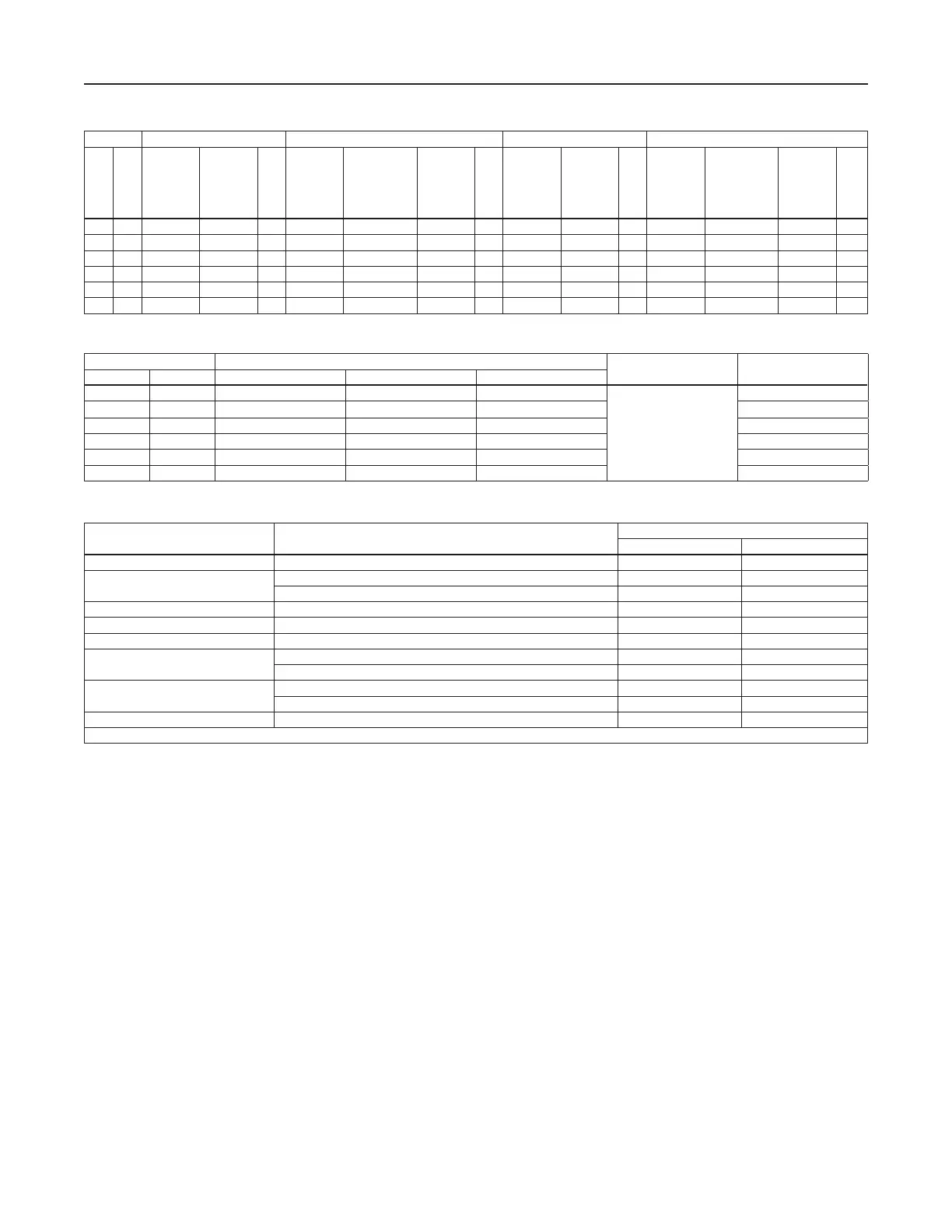
Table 5. Flow Coecients
ORIFICE 3/4 NPT NPS 1 / DN 25 BODY NPS 1-1/4 / DN 32 BODY NPS 2 / DN 50 BODY
In. mm
Wide-Open
C
g
for
External
Relief
Sizing
Wide-Open
C
v
for
External
Relief
Sizing
C
1
Wide-Open
C
g
for
External
Relief
Sizing
Wide-Open C
g
for External
Relief
Sizing for
Type 627OSX
only
Wide-Open
C
v
for
External
Relief
Sizing
C
1
Wide-Open
C
g
for
External
Relief
Sizing
Wide-Open
C
v
for
External
Relief
Sizing
C
1
Wide-Open
C
g
for
External
Relief
Sizing
Wide-Open C
g
for External
Relief
Sizing for
Type 627OSX
only
Wide-Open
C
v
for
External
Relief
Sizing
C
1
3/32 2.4 6.9 0.24 29.2 6.9 6.8 0.24 28.5 7.0 0.23 30.7 6.9 6.7 0.23 29.7
1/8 3.2 12.5 0.43 29.1 12.5 11.4 0.43 29.4 12.1 0.43 28.0 12.5 11.2 0.42 29.5
3/16 4.8 29 1.01 28.6 29 27 0.93 31.2 26 0.92 28.7 29 28.4 1.02 28.5
1/4 6.4 50 1.63 30.6 50 47.6 1.71 29.3 43 1.45 30.0 52 47.5 1.66 31.3
3/8 9.5 108 2.99 36.1 108 107 3.42 31.6 96 3.33 28.9 115 107.4 3.39 33.9
1/2 13 190 4.87 39.0 190 166.4 5.29 35.9 168 5.18 32.4 200 169.1 5.01 39.9
Table 6. IEC Sizing Coecients
ORIFICE SIZE X
T
F
D
F
L
In. mm 3/4 NPT Body NPS 1 / DN 25 Body NPS 2 / DN 50 Body
3/32 2.4 0.539 0.514 0.558
0.50
0.85
1/8 3.2 0.536 0.547 0.539 0.79
3/16 4.8 0.517 0.616 0.514 0.85
1/4 6.4 0.592 0.543 0.620 0.87
3/8 9.5 0.824 0.632 0.727 0.89
1/2 13 0.962 0.815 1.01 0.86
Table 7. Maximum Torque Values
KEY NUMBER
(1)
DESCRIPTION
MAXIMUM TORQUE
FOOT-POUNDS N•m
2 Orifice 25 34
3
Cap screw (with aluminum diaphragm casing) 16 22
Cap screw (with ductile iron or steel/stainless steel diaphragm casing) 25 34
18 Lever cap screw 7 9.5
22 Diaphragm connector nut 17 23
26 Guide retainer (for Types 627R, 627LR and 627MR only) 3 4.1
37
Spring case cap screw (with aluminum or ductile iron diaphragm casing) 7 9.5
Spring case cap screw (with steel/stainless steel diaphragm casing) 35 47
46
Diaphragm cap screw (with Type 627 or 627M) 7 9.5
Diaphragm cap screw (with Type 627H or 627HM) 14 19
75 Slam-Shut Valve orifice 25 34
1. Refer to Figures 7 through 13 for key number locations.
10
627 Series
 Loading...