Specifications (continued)
De-Icer System
See Figure 3 and Type 627M Regulator De-Icer
System Application section
Relief Indicator
For Types 627R, 627LR and 627MR
(see Figures 8, 9 and 11)
Spring Case Vent Connection
3/4 NPT with removable screened vent assembly
Approximate Weights
627 Series
Ductile Iron, Steel or Stainless steel Casings:
10 lbs / 5 kg
Aluminum Casing: 6.3 lbs / 3 kg
Type 627OSX
NPS 1 / DN 25: 40 lbs / 18 kg
NPS 2 / DN 50: 42 lbs / 19 kg
Principle of Operation
Refer to Figure 2. When downstream demand decreases,
the pressure under the diaphragm increases. This pressure
overcomes the regulator setting (which is set by a spring).
Through the action of the pusher post assembly, lever
and valve stem the valve disk moves closer to the orifice
and reduces gas flow. If demand downstream increases,
pressure under the diaphragm decreases. Spring force
pushes the pusher post assembly downward and the valve
disk moves away from the orifice.
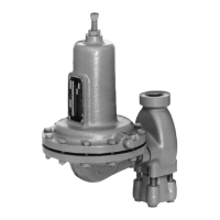
Product Description
Types 627 and 627H Direct-Operated Pressure Reducing
Regulators—The Types 627 and 627H regulators provide
economical pressure reducing control for a variety of
residential, commercial and industrial applications. The
regulator pitot tube located in a high velocity stream provides
dynamic boost that compensates for outlet pressure drop.
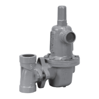
Type 627 Long Body—The Type 627 Long Body regulator
can be used as a drop-in replacement for existing Type 630
installations without the need to modify piping.
Internal Relief for Type 627R, 627LR or 627MR
Regulator—The Type 627R internal relief performance
values were obtained by removing the disk assembly
from the regulator. For the Type 627R, 627LR or 627MR
regulator, the internal relief across the diaphragm provides
overpressure protection in many applications. As outlet
pressures build up above the start-to-discharge point, the
diaphragm moves off the relief valve seat allowing the
excess pressure to bleed out through the screened vent.
For extra protection, should failure conditions exist which
would prevent normal operation of the regulator (for
example, disk broken off or disk erosion), the pusher
post contacts the lever retainer causing the relief valve
assembly to open. Since the diaphragm continues to rise
as downstream pressure builds, it opens the relief valve;
thereby, opening the valve. This internal relief may be
adequate for the application.
Downstream Control Line for Type 627M, 627HM, 627MR,
627MOSX or 627HMOSX Regulator—A Type 627M,
627HM, 627MR, 627MOSX or 627HMOSX regulator has a
blocking throat stem seal with O-rings and a 1/4 NPT control
line connection in the diaphragm case. A regulator with a
downstream control line is used for monitoring applications
or other applications where other equipment is installed
between the regulator and the pressure control point. The
stem seal separates the body outlet pressure from the
diaphragm case.
Type 627OSX— The Type 627OSX regulator with integral
slam-shut device can provide either overpressure (OPSO)
or overpressure (OPSO) and underpressure (UPSO)
protection by completely shutting off the flow of gas to the
downstream system.
Installation
Regulator operation within ratings does not preclude
the possibility of damage from debris in the lines or from
external sources. A regulator should be inspected for
damage periodically and after any overpressure condition.
Key numbers referenced in this section are shown in
Figures 7 through 13. Ensure that the operating temperature
capabilities listed in Specifications section are not exceeded.
Note
If the regulator is shipped mounted on
another unit, install that unit according to the
appropriate Instruction Manual.
Perform steps 1 through 6 for all types of regulators:
1. Only personnel qualified through training and
experience should install, operate or maintain
this regulator.
2. For a regulator that is shipped separately, make
sure that there is no damage to or foreign material in
the regulator.
3. Ensure that all tubing and piping have been blown free
of foreign debris.
4. The regulator may be installed in any position as long as
the flow through the body is in the direction indicated by
the arrow cast on the body.
3
627 Series
 Loading...