W4791
W4792
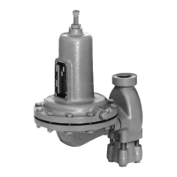
Figure 5. Stem Assemblies
DIAPHRAGM
CASING
(KEY 5)
LEVER
(KEY 15)
STEM (KEY 10)
STEM BACK-UP
RINGS
(KEY 12)
STEM O-RING
(KEY 11)
STEM GUIDE
(KEY 8)
DIAPHRAGM CASING
O-RING (KEY 4)
STABILIZER
(KEY 7)
BOOST
BODY (KEY 6)
PITOT TUBE
AND TAB FOR
TYPE 627 ONLY
DISK
ASSEMBLY
(KEY 9)
HAIR PIN
CLIP (KEY 13)
BODY
(KEY 1)
CAP
SCREW
(KEY 3)
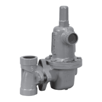
TYPES 627, 627H, 627R AND 627LR
BLOCKED THROAT
BACK-UP RINGS (KEY 45)
BLOCKED
THROAT
(KEY 43)
TYPES 627M, 627HM AND 627MR
BLOCKED THROAT
O-RINGS (KEY 44)
5. Install the replacement lever (key 15) into the lever
retainer (key 16) by inserting the lever pin (key 17).
Secure the lever assembly into the diaphragm casing
with the cap screws (key 18) and torque the cap screws
to 7 ft-lbs / 9.5 N•m.
If it is necessary to perform maintenance on the
diaphragm assembly, continue with steps 6 through 11
and step 20 for Types 627, 627H, 627M, 627HM and all
627OSX variations regulators or steps 12 through 19 for
Types 627R, 627LR and 627MR regulators.
Perform steps 6 through 11 for Types 627, 627H, 627M,
627HM and all 627OSX variations Regulators only:
6. For Types 627, 627H, 627M and 627HM regulators
(Figures 5 and 6), use steps 7 through 11 to
disassemble and reassemble the diaphragm assembly.
7. Remove the diaphragm head cap screw (key 46),
lower spring seat (key 31, Type 627 or 627M only) and
diaphragm head (key 24). On the Type 627H or 627HM,
remove the pusher post O-rings (key 52). Separate the
diaphragm (key 23) from the pusher post (key 19).
8. Install the diaphragm (key 23), in reverse order in
step 7, on the pusher post (key 19), insert and finger
tighten the diaphragm head cap screw (key 46).
9. Hook the pusher post on the lever (key 15), then turn
the diaphragm (key 23) to match the holes in the
diaphragm with the holes in the spring casing.
10. Unhook the pusher post from the lever (key 15) and
torque the diaphragm head cap screw (key 46) to
7 ft-lbs / 9.5 N•m for the Type 627 or 627M. On the
Type 627H or 627HM, torque the diaphragm head cap
screw to 14 ft-lbs / 19 N•m.
11. Hook the pusher post on the lever (key 15) and check
the hole alignment. If necessary, loosen the cap screw
(key 46) and reposition the diaphragm (key 23) on the
pusher post (key 19). Retorque the screw (see step 10).
Skip to step 20.
Perform steps 12 through 19 for Types 627R, 627LR and
627MR Regulators only:
12. For Types 627R, 627LR and 627MR regulators
(Figure 6), use steps 13 through 19 to disassemble and
reassemble the diaphragm assembly.
13. Remove the guide retainer (key 26) and separate the
diaphragm parts. Refer to Figure 6 for the sequence
of parts.
ORIFICE
(KEY 2)
12
627 Series
 Loading...